Zoom lens and unmanned aerial vehicle

A zoom lens and variable magnification lens technology, applied in the optical field, can solve the problems of difficult installation of the lens, increase in the length of the lens, etc., and achieve the effect of increasing the scope of application, increasing the zooming range, and reducing the moving range.

Pending Publication Date: 2022-06-24
JIAXING ZHONGRUN OPTICAL TECH
View PDF0 Cites 0 Cited by
  • Summary
  • Abstract
  • Description
  • Claims
  • Application Information

AI Technical Summary

Problems solved by technology

[0003] When a lens needs to be installed in an existing drone, the installed lens is usually small in size, but when the size of the lens is small, the zoom range of the zoom lens is also reduced. In order to increase the optical zoom ratio, the existing technology often It is necessary to expand the movement range of the group, so that the length of the lens will increase accordingly. At the same time, the larger movement range will cause the lens to be equipped with a large-sized motor to provide sufficient group driving force, and the lens will be difficult to install on the drone. middle

Method used


Image

  • Zoom lens and unmanned aerial vehicle
  • Zoom lens and unmanned aerial vehicle
  • Zoom lens and unmanned aerial vehicle

Examples


Embodiment 1

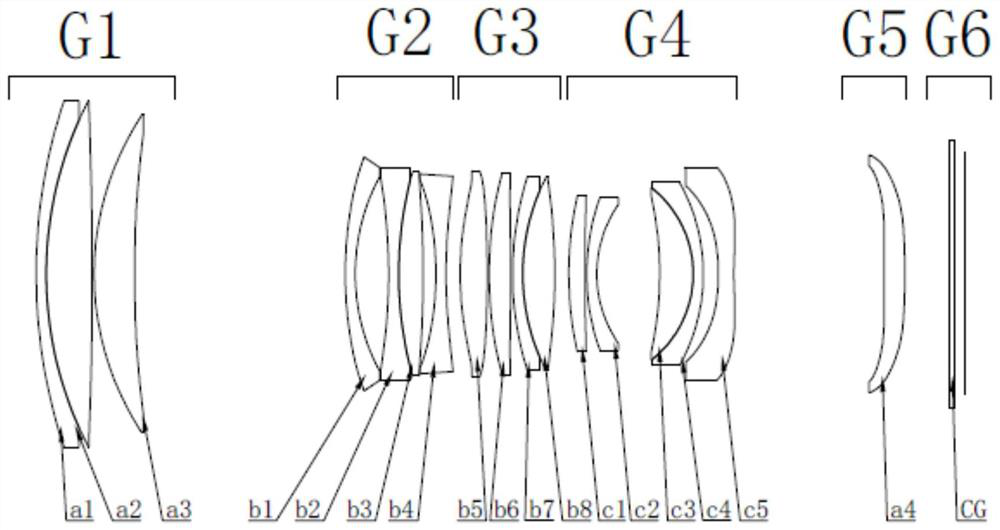
[0065] like figure 1 As shown, a zoom lens, the zoom lens includes sequentially from the object plane side to the image plane side:

[0066] The first fixed lens group G1 with positive refractive power, the first variable power group G2 with negative power, the second variable power group G3 with positive power, the focusing lens group G4 with negative power, the second variable power group with positive power Fixed lens group G5;

[0067] the first variable magnification group G2, the second variable magnification and the focusing lens group G4 move along the direction of the main optical axis of the zoom lens;

[0068] TTL<50mm;

[0069] Wherein, TTL is the total optical length of the zoom lens.

[0070] In this embodiment, through the limitation of the above structure, a zoom lens with high imaging quality can be realized with less structure, and the total optical length of the zoom lens is small, which is convenient for the above structure to be installed in the drone, ...

Embodiment 2

[0105] like Figure 1 to Figure 5 As shown, a zoom lens, the zoom lens includes sequentially from the object plane side to the image plane side:

[0106] The first fixed lens group G1 with positive refractive power, the first variable power group G2 with negative power, the second variable power group G3 with positive power, the focusing lens group G4 with negative power, the second variable power group with positive power The lens group G5 and the auxiliary assembly G6 are fixed.

[0107] The first fixed lens group G1 includes sequentially from the object plane side to the image plane side:

[0108] The first fixed lens a1 with negative refractive power, the second fixed lens a2 with positive refractive power, the third fixed lens a3 with positive refractive power, the first fixed lens a1 and the second fixed lens a2 are cemented.

[0109] The first variable magnification group G2 includes sequentially from the object plane side to the image plane side:

[0110] The first ...

Embodiment 4

[0177] a drone such as Figure 1 to Figure 10 As shown, it includes a zoom lens as described in any of the above embodiments, and an imaging element configured to receive an image formed by the zoom lens.


PUM


Abstract

The invention relates to the field of optics, in particular to a zoom lens and an unmanned aerial vehicle. The zoom lens sequentially comprises a first fixed lens group with positive focal power, a first zoom group with negative focal power, a second zoom group with positive focal power, a focusing lens group with negative focal power and a second fixed lens group with positive focal power from an object plane side to an image plane side, the first zoom group, the second zoom group and the focusing lens group move along the main optical axis direction of the zoom lens; tTL is less than 50mm; wherein TTL is the total optical length of the zoom lens. According to the technical scheme, the zoom lens with high imaging quality can be realized under the condition of fewer structures, and the total optical length of the zoom lens is smaller, so that the structures can be conveniently arranged in the unmanned aerial vehicle, and the application range of the zoom lens is expanded.

Description

technical field [0001] The invention relates to the field of optics, in particular to a zoom lens and an unmanned aerial vehicle. Background technique [0002] Unmanned aerial vehicle is referred to as "unmanned aerial vehicle", and the English abbreviation is "UAV". [0003] When a lens needs to be installed in the existing drone, the installed lens is usually small in size, but when the size of the lens is small, the zoom range of the zoom lens is also reduced. In order to increase the optical zoom magnification in the existing technology, the It is necessary to expand the movement range of the group, so that the length of the lens increases accordingly. At the same time, the larger movement range will cause the lens to be installed with a large-sized motor to provide sufficient driving force for the group, which makes it difficult to install the lens on the drone. middle. SUMMARY OF THE INVENTION [0004] The present invention will solve the existing technical problem...

Claims


Application Information

Patent Timeline
Patent Type & Authority Applications(China)
IPC IPC(8): G02B15/177G02B15/14G02B13/00G03B30/00
CPCG02B15/177G02B15/145121G02B13/006G02B13/009G03B30/00
Inventor 袁浩生马培培韩志俊沈佳
Owner JIAXING ZHONGRUN OPTICAL TECH
Why Eureka
Try Eureka