Image processing method and device, electronic equipment and storage medium

A technology of image processing and location information, which is applied in the computer field, can solve the problem of incompatibility between material and eye area, achieve real rendering effect, improve rendering efficiency, and save design cost

Pending Publication Date: 2022-06-24
BEIJING DAJIA INTERNET INFORMATION TECH CO LTD
View PDF0 Cites 0 Cited by
  • Summary
  • Abstract
  • Description
  • Claims
  • Application Information

AI Technical Summary

Problems solved by technology

[0004] The present disclosure provides an image processing method, device, electronic equipment, and storage medium to at least solve the problem of incompatibility between materials and eye regions

Method used


Image

  • Image processing method and device, electronic equipment and storage medium
  • Image processing method and device, electronic equipment and storage medium
  • Image processing method and device, electronic equipment and storage medium

Examples


Embodiment approach 3

[0124]As an optional embodiment 3 of step S304, generating target mesh vertices corresponding to the multiple mesh vertices according to the flip angle and the position information of the multiple mesh vertices, including: determining the first key point and the second key point Point connection; perform orthogonal projection processing on multiple mesh vertices on the connection line to obtain projection points corresponding to multiple mesh vertices; determine the corresponding multiple mesh vertices according to the flip angle and the position information of the projection points the target mesh vertex.

[0125] Specifically, orthogonal projection processing is performed on a plurality of mesh vertices on the connecting line to obtain projection points corresponding to the plurality of mesh vertices, wherein the projection points corresponding to the plurality of mesh vertices are all located on the connecting line. For details, please refer to Figure 5 , in the three-dim...

Embodiment approach 4

[0131] As an optional implementation manner 4 of step S304, generating target mesh vertices corresponding to the multiple mesh vertices according to the flip angle and the position information of the multiple mesh vertices includes: determining a specific mesh vertex from the multiple mesh vertices. Mesh vertex; wherein, the specific mesh vertex is any vertex of multiple mesh vertices or a preset vertex of multiple mesh vertices; determine the connection line between the first key point and the second key point, and Orthogonal projection processing is performed on the specific mesh vertex on the line to obtain the projection point corresponding to the specific mesh vertex; the target mesh vertex corresponding to the specific mesh vertex is determined according to the flip angle and the position information of the projection point; according to the first key point, The second key point and the target mesh vertex corresponding to the specific mesh vertex determine the target mesh...


PUM


Abstract

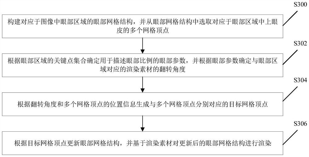
The invention relates to an image processing method and device, electronic equipment and a storage medium, and relates to the technical field of computers. The method comprises the following steps: constructing an eye grid structure corresponding to an eye region in an image, and selecting a plurality of grid vertexes corresponding to an upper eyelid in the eye region from the eye grid structure; determining an eye parameter for describing an eye proportion according to the key point set of the eye region, and determining an overturning angle of a rendering material corresponding to the eye region according to the eye parameter; generating target grid vertexes respectively corresponding to the plurality of grid vertexes according to the overturning angle and the position information of the plurality of grid vertexes; and updating the eye grid structure according to the target grid vertex, and rendering the updated eye grid structure based on the rendering material. Therefore, personalized updating of the eye grid structure can be realized, a more adaptive eye grid structure can be obtained, the rendering material can be more adaptive to the eye region, and the rendering effect is more real and natural.

Description

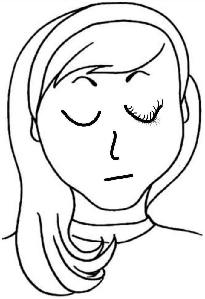
technical field [0001] The present disclosure relates to the field of computer technology, and in particular, to an image processing method, device, electronic device, and storage medium. Background technique [0002] In the effect processing for the eye area of ​​the character model, the rendering material is usually superimposed directly on the specific position of the face. However, the user's facial expressions are not static, and directly superimposing the rendering material on a specific position of the face may not fit every facial expression. For example, see figure 1 , when the user's eyes are closed, the eyelash material in the rendering material is directly superimposed on the eye area, which may easily lead to the problem that the material does not match the eye area. [0003] It should be noted that the information disclosed in the above Background section is only for enhancement of understanding of the background of the present disclosure and therefore does n...

Claims


Application Information

Patent Timeline
Patent Type & Authority Applications(China)
IPC IPC(8): G06T17/20G06T17/30G06T19/20G06T15/00
CPCG06T17/20G06T17/30G06T15/005G06T19/20
Inventor 胡跃祥黄亮
Owner BEIJING DAJIA INTERNET INFORMATION TECH CO LTD
Why Eureka
Try Eureka