
False touch correction system and method suitable for production line

A production line and false touch technology, applied in the field of false touch correction systems, can solve problems such as failure to completely shield interference clutter, system chain adverse reactions, and interference with the normal operation of production lines, to ensure accuracy, high precision, Avoid false trigger effects

Pending Publication Date: 2022-06-28
WULIANGYE +1
View PDF0 Cites 1 Cited by
  • Summary
  • Abstract
  • Description
  • Claims
  • Application Information

AI Technical Summary

Problems solved by technology

When clutter exists, industrial cameras and sensors will occasionally trigger falsely, that is, the clutter contains voltage frequency components that can trigger the camera’s reading circuit to work, causing the product to collect wrong data at incorrect positions. These false triggers may Cause chain adverse reactions in the system and interfere with the normal operation of the entire production line
At present, the main solutions are focused on circuit purification, such as adding filters, magnetic rings, etc. to the circuit, but it cannot completely shield the interference clutter

Method used


Image

  • False touch correction system and method suitable for production line
  • False touch correction system and method suitable for production line

Examples


Embodiment Construction

[0030] In order to make the objectives, technical solutions and advantages of the present invention clearer, the present invention will be further described in detail below with reference to the embodiments. It should be understood that the specific embodiments described herein are only used to explain the present invention, but not to limit the present invention.

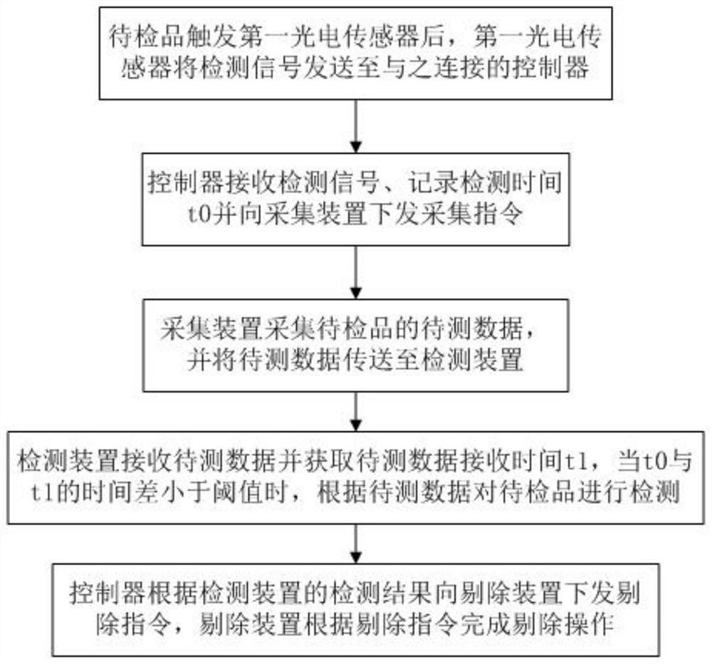
[0031] like figure 1 shown, false-touch correction systems for production lines, including:

[0032] The first photoelectric sensor: used to detect the arrival of the product to be inspected, and send the detection signal to the controller connected to it;

[0033] Controller: used to receive detection signals, record detection time t0, and issue acquisition instructions to acquisition devices, such as PLC;

[0034] Acquisition device: used to collect the data to be tested of the product to be tested, and transmit the data to be tested to the detection device;

[0035] Detection device: used to receive the data ...


PUM


Abstract

The invention relates to the technical field of production line detection, aims to solve the problem of product false rejection caused by false triggering of a detection device, and provides a false touch correction system suitable for a production line, which comprises a first photoelectric sensor, a controller, an acquisition device and the detection device. The method comprises the following steps: 1, after a to-be-detected product triggers a first photoelectric sensor, the first photoelectric sensor sends a detection signal to a controller connected with the first photoelectric sensor; 2, the controller receives the detection signal, records the detection time t0 and issues an acquisition instruction to the acquisition device; 3, the acquisition device acquires to-be-detected data of the to-be-detected product and transmits the to-be-detected data to the detection device; 4, the detection device receives the to-be-detected data and obtains the receiving time t1 of the to-be-detected data, when the time difference between t0 and t1 is smaller than a threshold value, the trigger is valid, the detection device detects the to-be-detected product according to the to-be-detected data, otherwise, the trigger is invalid, and the detection device ignores the to-be-detected data. By adopting the mode, the problem of false elimination caused by false triggering can be effectively avoided.

Description

technical field [0001] The invention relates to the technical field of production line detection, in particular to a false touch correction system and method suitable for production lines. Background technique [0002] In the process of industrial production, testing is the most critical link to ensure the quality of products leaving the factory. Automated testing has become a key link in the transformation of intelligent manufacturing. Equipment instead of manual testing has many advantages. However, the electrical environment in the industrial field is harsh, and there are many industrial clutter. The extensive use of frequency conversion equipment further deteriorates the electrical environment in the industrial field, which brings great challenges to the operation of precision testing equipment, especially visual cameras. The detection device basically works in the trigger mode, and the photoelectric sensor senses the arrival of the object to be inspected and sends a spe...

Claims


Application Information

Patent Timeline
IPC IPC(8): B07C5/342B07C5/36
CPCB07C5/3422B07C5/361B07C5/362Y02P90/02
Inventor 郑佳刘从军乔宗伟赵东彭自铭刘多涛张睿欧意雷波
Owner WULIANGYE
Learn More