Probe fixed-distance control device for eddy current flaw detection of special-shaped pipe fitting and control method of probe fixed-distance control device
A control device, eddy current flaw detection technology, applied in measuring devices, instruments, scientific instruments, etc., can solve problems such as low detection accuracy
- Summary
- Abstract
- Description
- Claims
- Application Information
AI Technical Summary
Problems solved by technology
Method used
Image
Examples
Embodiment 1
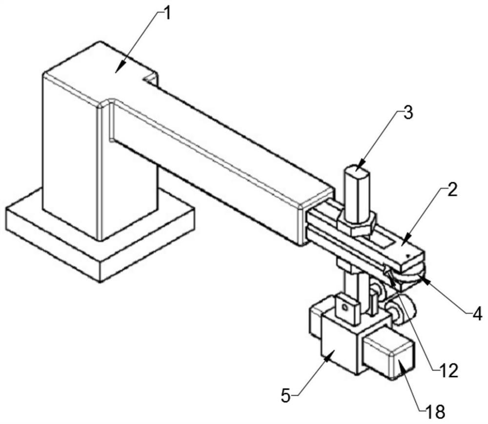
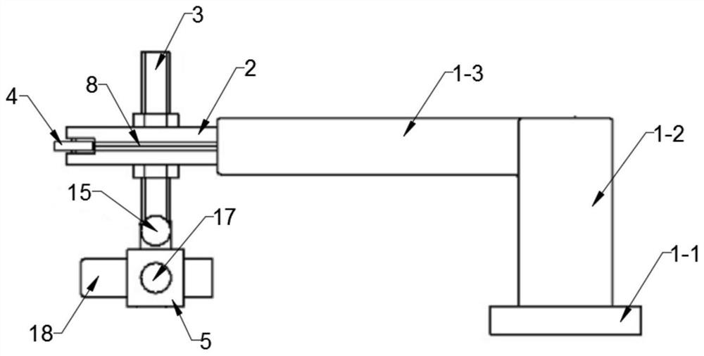
[0044] A probe distance control device for the pipe under test, such as figure 1 and figure 2 As shown in the figure, it includes a fixed frame 1, a horizontal rod 2 installed on the fixed frame 1 through a mounting assembly, a vertical rod 3 vertically installed on the free end of the cross rod 2, a vertical rod 3 installed on the The roller 4 on the free end of the horizontal bar 2 and the probe clamp 5 installed on the lower end of the vertical bar;
[0045] Adjustable vertical installation means that the vertical rod 3 can be adjusted vertically in two dimensions, the horizontal direction and the height direction, and the probe clamp 5 and the probe 18 installed thereon are located directly below the horizontal rod 2 .
[0046] The installation assembly includes a guide rail 7, a guide rail groove 8 and a compression spring 14; the guide rail 7 and the compression spring 14 are installed in the inner cavity 6 of the fixing frame 1; the guide rail groove 8 is arranged on ...
Embodiment 2
[0048] This embodiment is based on the probe distance control device in Embodiment 1, and introduces its control method.
[0049] like Figure 11 As shown, the detection coil 20 is wound around the to-be-measured part of the pipe material 19 to be measured;
[0050] Adjust the position of the tested pipe 19 so that the roller 4 is always in contact with the outer wall of the tested pipe 19 when the tested pipe 19 rotates along the central axis;
[0051] According to the shape and size of the pipe material 19 to be tested, adjust the horizontal position and height position of the vertical rod 3 to the appropriate detection position; install the probe 18 on the probe clamp 5 and adjust the distance between the probe clamp 5 and the vertical rod 3 according to the angle of the side to be tested the angle between
[0052] The pipe material 19 to be tested rotates along the central axis, and the probe 18 performs flaw detection on the entire circumferential direction of the pipe ...
Embodiment 3
[0055] This embodiment is based on Embodiment 1, and introduces its detailed structure.
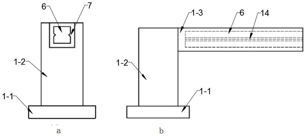
[0056] like image 3As shown, the fixing frame 1 includes a base 1-1, a vertical part 1-2 and a horizontal part 1-3; the base 1-1 is fixed on a flat position such as a desktop or the ground, so that the horizontal part 1-3 remains stable and level;
[0057] One end of the horizontal portion 1-3 away from the vertical portion 1-2 is open and extends inward to form an inner cavity 6 with a square cross-section; the left and right side walls of the inner cavity 6 are respectively provided with guide rails 7;
[0058] like Figure 4 As shown, the outer edge of the cross-section of the cross-bar 2 is square and matches the inner cavity 6; the left and right sides of the cross-bar 2 are respectively provided with guide rail grooves 8; the guide rail grooves 8 are matched with the guide rails 7, so that the cross bar 2 and the horizontal parts 1-3 are horizontally slidably installed;
[0059...
PUM
 Abstract
Description
Claims
Application Information
 - R&D
- Intellectual Property
- Life Sciences
- Materials
- Tech Scout
- Unparalleled Data Quality
- Higher Quality Content
- 60% Fewer Hallucinations
Browse by: Latest US Patents, China's latest patents, Technical Efficacy Thesaurus, Application Domain, Technology Topic, Popular Technical Reports.
© 2025 PatSnap. All rights reserved.Legal|Privacy policy|Modern Slavery Act Transparency Statement|Sitemap|About US| Contact US: help@patsnap.com


