Transformer low-voltage side binding post protective cover and installation clamp thereof

A technology of transformer low-voltage side and installation fixture, which is applied in the direction of transformer/inductor coil/winding/connection, transformer/inductor shell, inductor/transformer/magnet manufacturing, etc. and other problems, to achieve the effect of fast and easy installation and improve the degree of fit

Pending Publication Date: 2022-06-28
广东粤艺电力科技有限公司
View PDF0 Cites 0 Cited by
  • Summary
  • Abstract
  • Description
  • Claims
  • Application Information

AI Technical Summary

Problems solved by technology

[0002] The transformer is used for the power equipment of the overhead distribution network line transmission operation, which is suitable for the urban power grid and the rural power grid; the low-voltage side of the transformer is provided with a terminal, and it is often subject to environmental erosion and interference from small animals when used outdoors, so it is often It will lead to the problem of power failure. In order to solve this problem, a protective cover is usually installed on the low-voltage side terminal, but the installation of the existing protective cover is relatively complicated, and it is difficult to meet the installation requirements of different installation environments, resulting in the protective cover after installation. It is difficult to fit the terminal, which may easily lead to the problem of the protective cover falling off

Method used


Image

  • Transformer low-voltage side binding post protective cover and installation clamp thereof
  • Transformer low-voltage side binding post protective cover and installation clamp thereof
  • Transformer low-voltage side binding post protective cover and installation clamp thereof

Examples


Embodiment Construction

[0028] The present invention provides a protective cover for the low-voltage side terminal of a transformer. In order to make the purpose, technical solutions and effects of the present invention clearer and clearer, the present invention is further described in detail below with reference to the accompanying drawings and examples. It should be understood that the specific embodiments described herein are only used to explain the present invention, but not to limit the present invention.

[0029] In the description of the present invention, it should be understood that the orientation or positional relationship indicated by the terms "middle", "inside", "outside", etc. is the orientation or positional relationship of the present invention based on the accompanying drawings, and is only for the convenience of describing the present invention and simplified descriptions. In addition, the terms "first", "second" and "third" are used for descriptive purposes only, and should not b...


PUM


Abstract

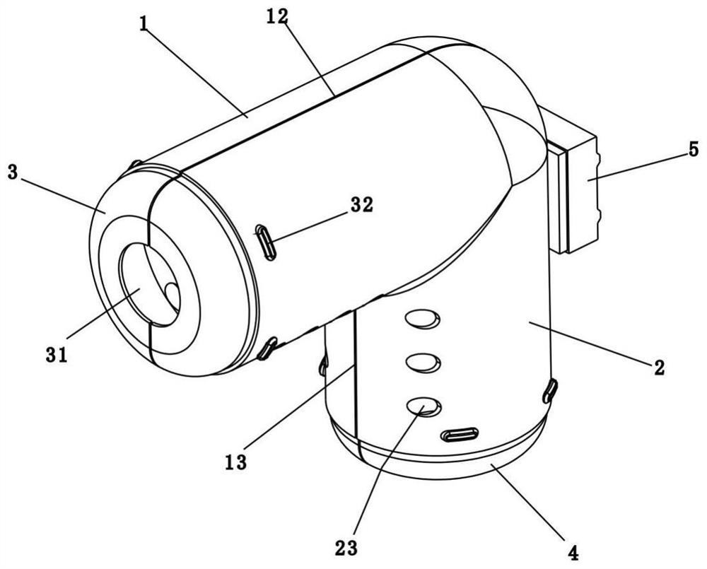
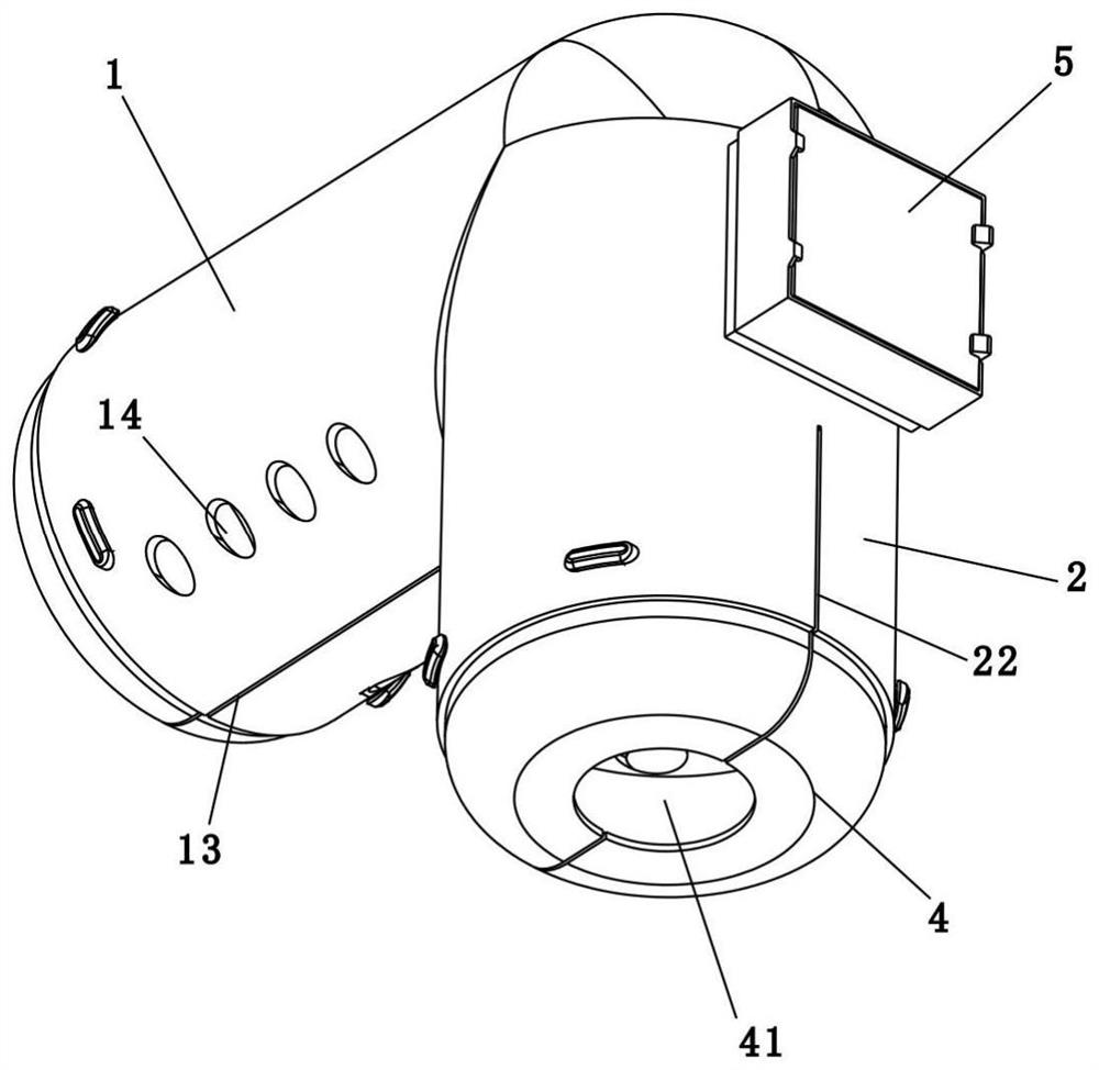
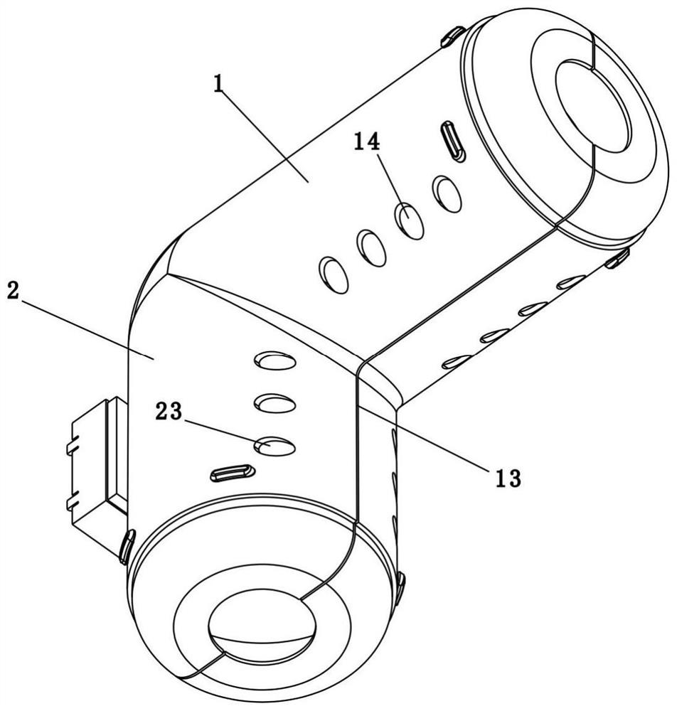
The transformer low-voltage side binding post protective cover comprises a first cylinder body and a second cylinder body, the first cylinder body is horizontally arranged on one side of the top of the second cylinder body, the first cylinder body is provided with a first isolation cavity with an opening facing one side, and the second cylinder body is provided with a second isolation cavity with an opening facing the lower portion; a first slot is formed in the top of the first barrel, a second slot is formed in the bottom of the first barrel, the second slot extends to the opening of the second isolation cavity, and a third slot is formed in the side, away from the first barrel, of the second barrel; through the first cylinder body and the second cylinder body which are perpendicular to each other, the installation requirements of the low-voltage side binding post and the cable are met, so that the fitting degree of the low-voltage side binding post and the cable is improved; during installation, through cooperation of the first slot, the second slot and the third slot, the first cylinder body and the second cylinder body are expanded to a certain opening degree, a low-voltage side binding post and a cable are clamped in the first isolation cavity and the second isolation cavity, and the whole installation process is rapid, simple and convenient.

Description

technical field [0001] The invention relates to the technical field of electric power equipment, in particular to a protective cover of a low-voltage side terminal of a transformer and an installation fixture thereof. Background technique [0002] Transformer is a power equipment used for power transmission operation of overhead distribution network lines, which is suitable for urban power grids and rural power grids; the low-voltage side of the transformer is provided with a terminal, which is often eroded by the environment and interfered by small animals when used outdoors, so it is often It will lead to the problem of power failure. In order to solve this problem, a protective cover is usually installed on the low-voltage side terminal. However, the installation of the existing protective cover is complicated, and it is difficult to meet the installation requirements of different installation environments. It is difficult to fit with the terminal, which may easily lead t...

Claims


Application Information

Patent Timeline
IPC IPC(8): H01F27/29H01F27/02H01F41/00B25B11/02
CPCH01F27/29H01F27/02H01F41/00B25B11/02
Inventor 李达钊邓艺军冼玉桃梁为杭毕文龙
Owner 广东粤艺电力科技有限公司
Why Eureka
Try Eureka