
Folding screen middle frame structure and display equipment

A frame structure and frame technology, which is applied in branch office equipment, telephone structure, electrical components, etc., can solve problems such as poor height and size, large gaps, and weak left and right frame structures

Pending Publication Date: 2022-06-28
DONGGUAN CHANGYING PRECISION TECH CO LTD
View PDF0 Cites 0 Cited by
  • Summary
  • Abstract
  • Description
  • Claims
  • Application Information

AI Technical Summary

Problems solved by technology

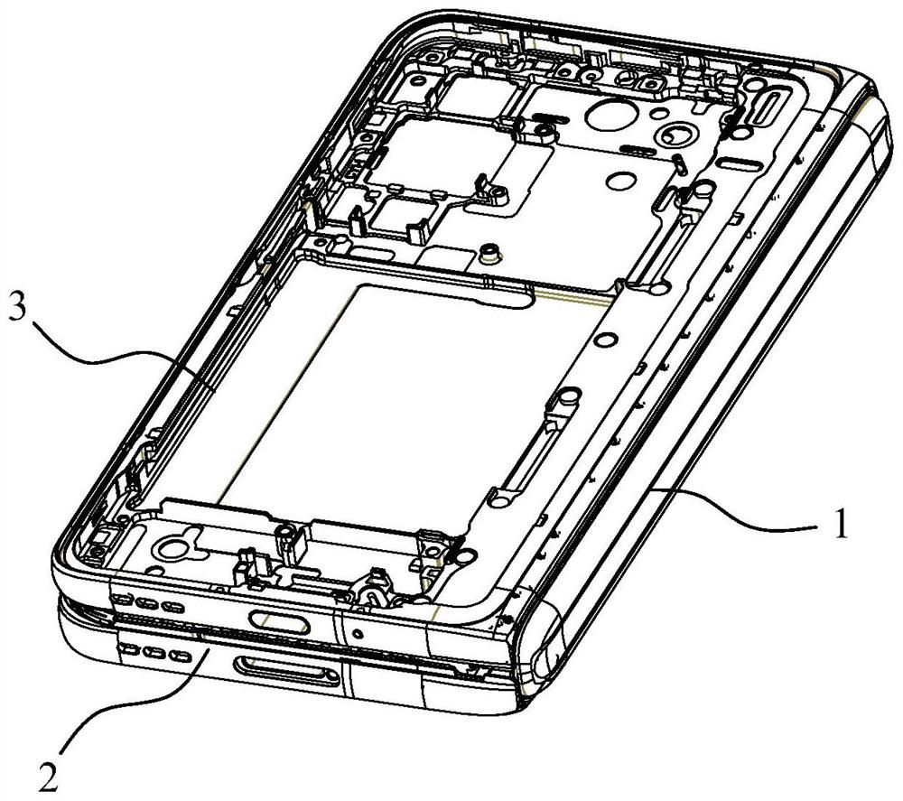
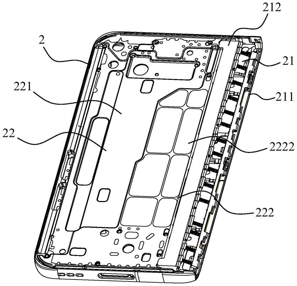
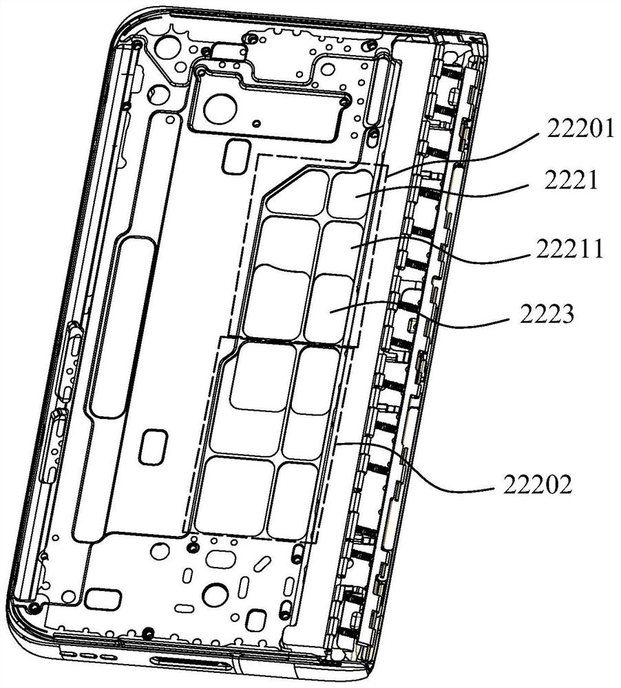
However, the existing folding screens have the following problems: the assembly requirements between the left and right frames of the folding screen and the DECO decoration are high (the fit gap is 0.16mm), and the structures of the left and right frames are weak and easy to deform. Exceeding the design requirements (the general design standard is straightness ≤ 0.05mm, and the convexity of the center cannot exceed 0.05mm), which will make the edges of the frame shaft installation area prone to the outside of the frame after the frame is assembled with the shaft and folded. Protruding deformation, resulting in too large gap between the shaft and the frame after assembly, affecting assembly, appearance and easy dust entry
In addition, the position where the screen installation area is away from the shaft installation area is also prone to protrude to the outside of the frame
[0003] At present, there is no better way to improve in the industry. Most of them mainly adjust the processing method, processing parameters, add stress relief or increase the shaping process, etc., but the effect is not very good and the cost is high.
However, due to the fact that mobile phones are becoming lighter and thinner and their structures are relatively weak, the requirements for waterproofing are getting higher and higher. If the shaping process is used, it will easily cause poor relative height and poor waterproofing

Method used


Image

  • Folding screen middle frame structure and display equipment
  • Folding screen middle frame structure and display equipment
  • Folding screen middle frame structure and display equipment

Examples


Embodiment Construction

[0033] In order to facilitate understanding of the present invention, the present invention will be described more fully hereinafter with reference to the related drawings. Preferred embodiments of the invention are shown in the accompanying drawings. However, the present invention may be embodied in many different forms and is not limited to the embodiments described herein. Rather, these embodiments are provided so that a thorough and complete understanding of the present disclosure is provided.

[0034] It should be noted that when an element is referred to as being "fixed to" another element, it can be directly on the other element or intervening elements may also be present. When an element is referred to as being "connected" to another element, it can be directly connected to the other element or intervening elements may also be present.

[0035] Unless otherwise defined, all technical and scientific terms used herein have the same meaning as commonly understood by one...


PUM


Abstract

The invention relates to a folding screen middle frame structure and display device.The folding screen middle frame structure comprises a rotating shaft, a first frame body and a second frame body, and the first frame body and the second frame body are arranged on the two opposite sides of the rotating shaft respectively and rotationally connected with the rotating shaft; a first rotating shaft surface is formed on the inner side, close to the edge of the rotating shaft, of the first frame body, and the first rotating shaft surface gradually protrudes towards the inner side of the first frame body from the edge to the center; a second rotating shaft surface is formed on the inner side, close to the edge of the rotating shaft, of the second frame body, and the second rotating shaft surface gradually protrudes towards the inner side of the second frame body from the edge to the center. According to the middle frame structure of the folding screen, the rotating shaft surfaces of the two frame bodies are changed from the existing planes into the curved surfaces which are smoothly and upwards convex from the edges to the centers, so that the centers of the rotating shaft surfaces are higher than the edges, gaps between the rotating shafts and the frame bodies after the rotating shafts are assembled are structurally improved, and bad product deformation is reduced.

Description

technical field [0001] The present invention relates to the technical field of display devices, in particular to a middle frame structure of a folding screen and a display device. Background technique [0002] The folding screen includes a middle frame and a screen body. The middle frame includes a rotating shaft and two frame bodies. The two frame bodies are respectively located on both sides of the rotating shaft and are rotatably connected with the rotating shaft, so that the middle frame can be folded under the driving of the screen body. However, the existing folding screen has the following problems: the assembly requirements between the left and right frame bodies of the folding screen and the DECO decorative parts are high (the matching gap is 0.16mm), and the structure of the left and right frame bodies is weak and easily deformed. Exceeding the design requirements (the general design standard is that the straightness is ≤0.05mm, and the convexity of the center cann...

Claims


Application Information

Patent Timeline
IPC IPC(8): H04M1/02
CPCH04M1/0216H04M1/0268
Inventor 唐斌张亮宇肖琦张伟通
Owner DONGGUAN CHANGYING PRECISION TECH CO LTD
Learn More