
Automatic flaw detection device for steel wire rope

A flaw detection device and steel wire rope technology, which is applied in the field of steel wire rope flaw detection, can solve problems such as inability to adjust flaw detection equipment, shadows in flaw detection equipment detection, and inaccurate detection.

Inactive Publication Date: 2022-07-01
南通市江海钢绳有限公司
View PDF9 Cites 2 Cited by
  • Summary
  • Abstract
  • Description
  • Claims
  • Application Information

AI Technical Summary

Problems solved by technology

[0004] However, the above-mentioned patents still have the following problems. First, when the steel wire rope is inspected for flaws, there are bends or warped edges on the steel wire rope, resulting in inaccurate detection during subsequent flaw detection. Second, when the steel wire rope is inspected for flaws, due to The steel wire rope will be coated with lubricating oil and other lubricants when it is used, and it cannot be cleaned. The presence of lubricating oil will cause shadows in the inspection of the flaw detection equipment, which will affect the accuracy of flaw detection; Adjust the position of the flaw detection equipment as needed, the steel wire rope at the bottom of the flaw detection equipment cannot perform flaw detection, resulting in incomplete flaw detection

Method used


Image

  • Automatic flaw detection device for steel wire rope
  • Automatic flaw detection device for steel wire rope
  • Automatic flaw detection device for steel wire rope

Examples


Embodiment Construction

[0033] In order to make the objectives, technical solutions and advantages of the present invention clearer, the technical solutions of the present invention will be clearly and completely described below with reference to the specific embodiments of the present invention and the corresponding drawings. Obviously, the described embodiments are only some, but not all, embodiments of the present invention. Based on the embodiments of the present invention, all other embodiments obtained by those of ordinary skill in the art without creative efforts shall fall within the protection scope of the present invention.

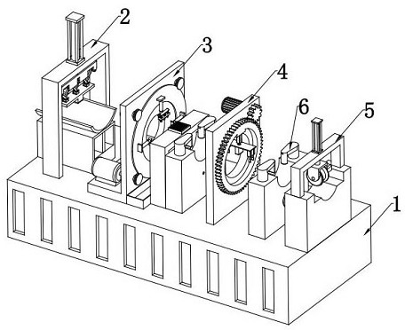
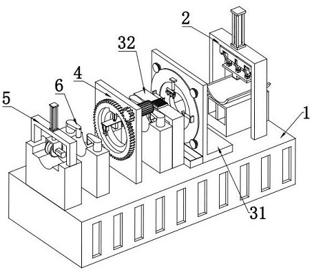
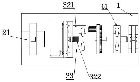
[0034] Combine below Figure 1 to Figure 9 As shown in the figure, the embodiment of the present invention provides an automatic flaw detection device for wire ropes, which includes an installation platform 1, and also includes a wire rope leveling component 2, a wire rope cleaning component 3, a wire rope flaw detection component 4, and a wire rope moving component 5 ...


PUM


Abstract

The invention discloses an automatic steel wire rope flaw detection device, which belongs to the technical field of steel wire rope flaw detection, and comprises a mounting table, and a steel wire rope leveling assembly, a steel wire rope cleaning assembly, a steel wire rope flaw detection assembly, a steel wire rope moving assembly and two steel wire rope fixing assemblies which are arranged on the mounting table, the steel wire rope leveling assembly is located at the feeding end of the mounting table, the steel wire rope cleaning assembly is located beside the steel wire rope leveling assembly, the steel wire rope flaw detection assembly is located in the middle of the mounting table, the two steel wire rope fixing assemblies are symmetrically arranged, and the two steel wire rope fixing assemblies are located between the steel wire rope flaw detection assemblies. The steel wire rope moving assembly is located at the discharging end of the mounting table. Through the steel wire rope flaw detection assembly, all-directional flaw detection operation can be conducted on the steel wire rope in the circumferential direction, the applicability of the device is improved, and flaw detection operation can be conducted on steel wire ropes of different sizes.

Description

technical field [0001] The invention relates to the technical field of wire rope flaw detection, in particular to an automatic flaw detection device for wire ropes. Background technique [0002] Wire ropes are widely used in mining, lifting, ropeway, port, marine and other operation sites. Since the wire rope will have defects such as broken wire, wear, corrosion and deformation after long-term use, in order to ensure the safety of on-site operators, equipment and lifting objects, it is necessary to regularly inspect the wire rope. [0003] For example, the publication number CN110006990A relates to a portable wire rope flaw detection equipment. The outside of one magnetic head of the flaw detection equipment is provided with a control compartment, and the control compartment is provided with a control board, a battery and a motor drive board, and the outside of the other magnetic head is provided with a handle. The top of the magnetic head is provided with a connecting sea...

Claims


Application Information

Patent Timeline
Patent Type & Authority Applications(China)
IPC IPC(8): G01N33/2045G01N1/34B08B1/00B08B1/04B08B3/02F26B21/00
CPCG01N33/2045G01N1/34B08B3/02F26B21/004B08B1/12B08B1/32
Inventor 孙巍巍
Owner 南通市江海钢绳有限公司
Learn More