
Communication cable detection equipment and detection method thereof

A technology for communication cables and testing equipment, applied in the field of cables, can solve the problems that the skin of communication cables cannot be automatically detected, the marking cannot be completed synchronously with the detection, and errors can be solved.

Pending Publication Date: 2022-07-05
赵文迪
View PDF1 Cites 0 Cited by
  • Summary
  • Abstract
  • Description
  • Claims
  • Application Information

AI Technical Summary

Problems solved by technology

[0006] In order to make up for the deficiencies in the prior art, a communication cable detection device and its detection method proposed by the present invention solve the problem that the communication cable skin cannot be automatically detected, and the marking of the damaged surface after detection cannot be completed synchronously with the detection, which needs to be divided into several steps , there will still be errors in the process

Method used


Image

  • Communication cable detection equipment and detection method thereof
  • Communication cable detection equipment and detection method thereof
  • Communication cable detection equipment and detection method thereof

Examples


Embodiment approach

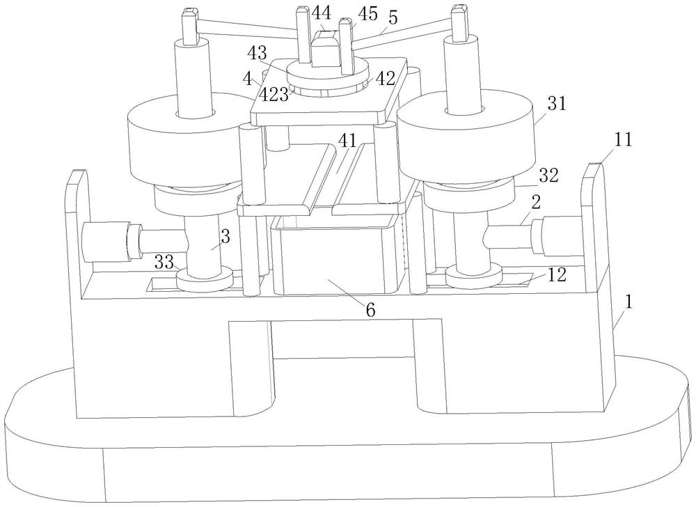
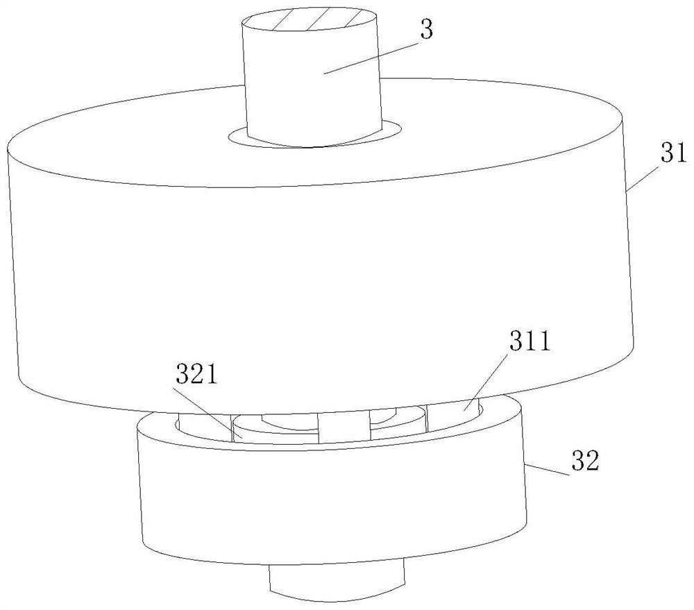
[0033] As an embodiment of the present invention, a tray 32 is fixedly installed on the outer wall of the moving rod 3; a sliding rod 311 is fixedly installed at the bottom of the drum 31; the tray 32 is located at the bottom of the drum 31, and the top of the tray 32 is provided with Slideway 321; the slide bar 311 slides inside the slideway 321; during operation, when the cable passes between the two rollers 31, the two rollers 31 will rotate. Restricting the direction may cause the drum 31 to float up and down, making the contact surface between the drum 31 and the cable uneven, resulting in inaccurate cable detection, and changing the rotation of the drum 31 into the rotation of the slide bar 311 inside the slideway 321, so that the drum 31 rotates It is more stable, and the slideway 321 will exert an external force on the drum 31 in the vertical direction, so that the drum 31 will not be laterally deflected, and the accuracy of the detection of the cable skin by the drum 3...


PUM


Abstract

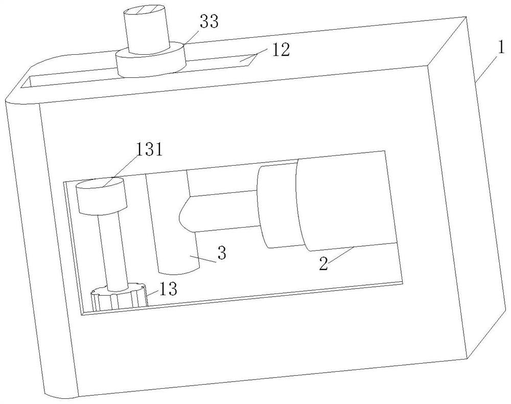
The invention belongs to the technical field of cables, and particularly relates to communication cable detection equipment and a detection method thereof.The communication cable detection equipment comprises a box body and a supporting plate fixedly installed at the top of the box body; a telescopic rod is fixedly mounted on the side wall of the supporting plate, and the telescopic rod has elasticity; a moving rod is fixedly mounted on the side wall of the telescopic rod; a roller is movably mounted on the outer wall of the moving rod; stand columns are fixedly mounted at the top of the rotary table and the top of the movable rod; the stand columns are fixedly connected through connecting rods. A cable is pulled through an external traction mechanism, the cable can drive the rollers to rotate in the pulling process, when a cable skin damage area moves to the position between the two rollers, the rollers can move towards the rollers under the action of the elastic force of the telescopic rods, the cable is subjected to speed reduction limitation through the rollers, and the effect of detecting the cable skin is achieved; the problem that the cable skin is not easy to detect is solved.

Description

technical field [0001] The invention belongs to the technical field of cables, in particular to a communication cable detection device and a detection method thereof. Background technique [0002] A cable is a power or signal transmission device, usually a rope-like cable formed by twisting several or several groups of wires. Has a highly insulating cover. The cable has the characteristics of inner energization and outer insulation. [0003] For example, a Chinese patent with application number CN202010802567.6 discloses a cable skin rupture detection device, which includes a casing, and a detection cavity whose left end communicates with the outside is provided in the casing, and a spray head provided in the detection cavity, The spray head can spray insulating glue to repair the broken cable, and the glue has a color to facilitate subsequent investigation. The return spring is provided with a fixed plate and a fixed bottom plate, which can connect the cable Fixing and w...

Claims


Application Information

Patent Timeline
Patent Type & Authority Applications(China)
IPC IPC(8): G01N19/00
CPCG01N19/00
Inventor 赵文迪陈辰
Owner 赵文迪
Learn More