Television remote controller with child lock
A TV remote control and remote control technology, which is applied in the field of remote control, can solve the problems of short service life of remote control, decrease of spring elasticity, affecting normal use, etc., and achieve the effects of improving battery life, buffering and stability
- Summary
- Abstract
- Description
- Claims
- Application Information
AI Technical Summary
Problems solved by technology
Method used
Image
Examples
Embodiment 1
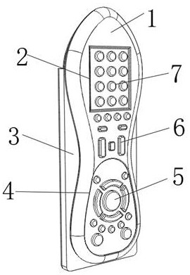
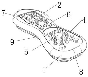
[0037] refer to Figure 1-5 , The present invention provides a TV remote control with a child lock, including a remote control body 1, the middle of the left and right sides of the remote control body 1 is provided with an arc-shaped groove 9, and the middle of the bottom end of the remote control body 1 is provided with a charging interface 8. A groove 2 is arranged above the other side of the main body 1, a key area 7 is arranged inside the groove 2, a key slot 4 is arranged under the other side of the remote controller body 1, and a first function is arranged inside the key slot 4. Zone 5, the middle of the other side of the remote control body 1 is provided with a second functional zone 6, the charging plug 13 adopts a Type-C plug, the charging interface 8 adopts a Type-C interface, and the distance between the charging plug 13 and the internal power supply of the shell 3 is The electrical connection is an electrical connection between the charging interface 8 and the inte...
Embodiment 2
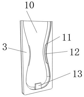
[0040] In this embodiment, on the basis of the structure disclosed in Embodiment 1, one side of the remote control body 1 is arranged inside the slot 10 , the slot 10 is arranged in the middle of one side of the casing 3 , and the casing 3 is left and right. A telescopic slot 11 is arranged on the inner wall of the middle part of both sides, a telescopic plate 12 is arranged inside the telescopic slot 11, and a plurality of sliding bars 17 are fixedly connected on the opposite side between the two telescopic plates 12, and the other side of the sliding bar 17 is fixed. One end penetrates through the chute 14 and is fixedly connected to the limit block 15, and the limit block 15 is slidably connected to the inside of the chute 14. The shape of the slot 10 is the same as that of one side of the remote control body 1, and the other side of the housing 3 is provided with a For the anti-skid pattern, the other side of the remote control body 1 is slidingly connected with the inner w...
Embodiment 3
[0043]In this embodiment, on the basis of the structures disclosed in Embodiments 1 and 2, a return spring 16 is provided on a section of the outer wall of the sliding rod 17 located inside the sliding slot 14, and the inner wall in the middle of the bottom end of the slot 10 is fixedly connected with a In the charging plug 13, one end of the return spring 16 is fixedly connected to one side of the limit block 15, and the other end of the return spring 16 is fixedly connected to the side of the chute 14 away from the limit block 15. The other side of the telescopic plate 12 is set in an arc shape, and the other side of the telescopic plate 12 is in contact with the arc groove 9. Under the action of the elastic force of the sliding groove 14 itself, the sliding rod 17 makes the expansion and contraction The plate 12 is in contact with the arc-shaped groove 9 so as to be engaged with the remote control body 1 , thereby improving the stability of the remote control body 1 during c...
PUM
 Abstract
Description
Claims
Application Information
 - R&D
- Intellectual Property
- Life Sciences
- Materials
- Tech Scout
- Unparalleled Data Quality
- Higher Quality Content
- 60% Fewer Hallucinations
Browse by: Latest US Patents, China's latest patents, Technical Efficacy Thesaurus, Application Domain, Technology Topic, Popular Technical Reports.
© 2025 PatSnap. All rights reserved.Legal|Privacy policy|Modern Slavery Act Transparency Statement|Sitemap|About US| Contact US: help@patsnap.com


