Supercharge Your Innovation With Domain-Expert AI Agents!

Energetic material filling device

A filling device and filling technology, applied in the directions of transportation, packaging, loading/unloading, etc., can solve the problems of charge quality defects, limited equipment adaptability, low filling density, etc., achieve continuous high-efficiency dense filling, and reduce charge quality defects , Improve the effect of packing density

Pending Publication Date: 2022-07-12
中国兵器装备集团自动化研究所有限公司
View PDF0 Cites 0 Cited by
  • Summary
  • Abstract
  • Description
  • Claims
  • Application Information

AI Technical Summary

Problems solved by technology

[0002] At present, in the field of energetic material packaging and warhead charging, in the process of compact packaging and dense filling / charging of energetic materials, many processes are involved, the filling is difficult, the quality of the charge is defective, and the filling process There are huge potential safety hazards. How to reasonably combine various technological processes to improve the quality and filling density of the charge and further reduce the potential safety hazards in the charge and filling process has become an urgent need for all military units.
[0003] In the existing technology, there are collision extrusion and static electricity accumulation in the process of filling and charging, and the adaptability of the equipment is limited, resulting in problems such as defective charging quality, low filling density, and potential safety hazards.

Method used


Image

  • Energetic material filling device
  • Energetic material filling device
  • Energetic material filling device

Examples


Embodiment 1

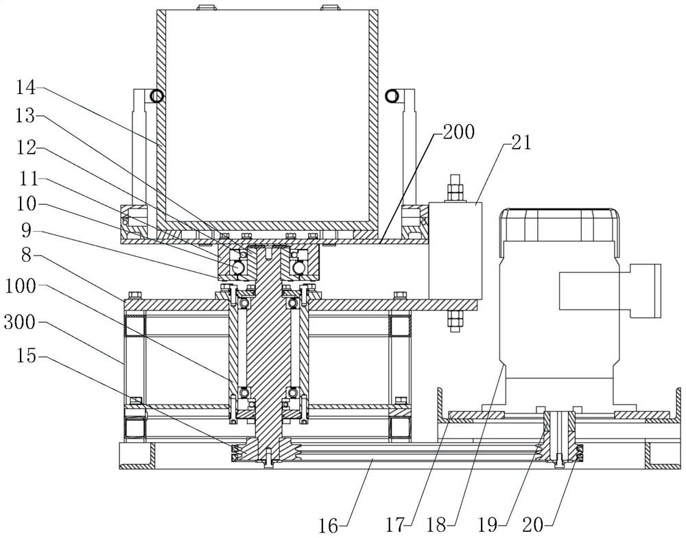
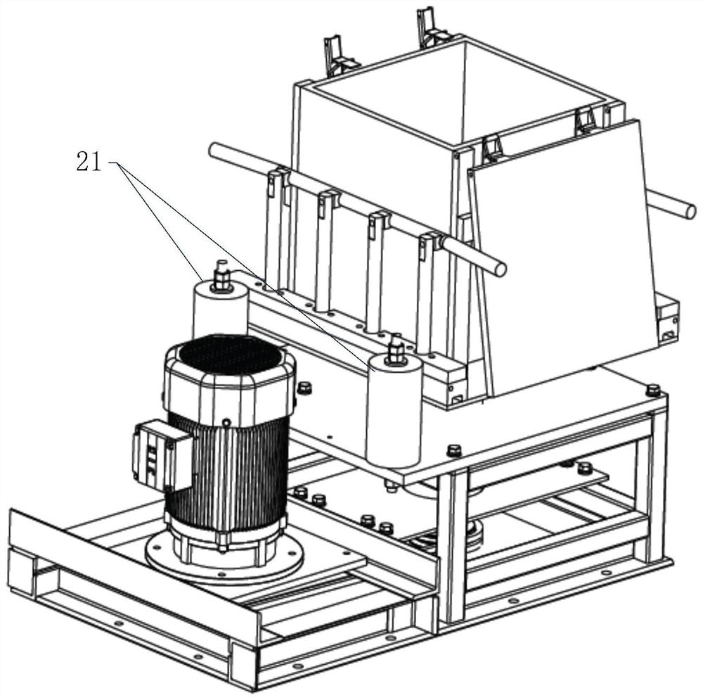
[0048] like Figure 1-Figure 4 As shown, an energetic material filling device includes a driving mechanism, a transmission mechanism 100, an eccentric block 13, a buffer column 21, a filling platform 200 and a frame 300:

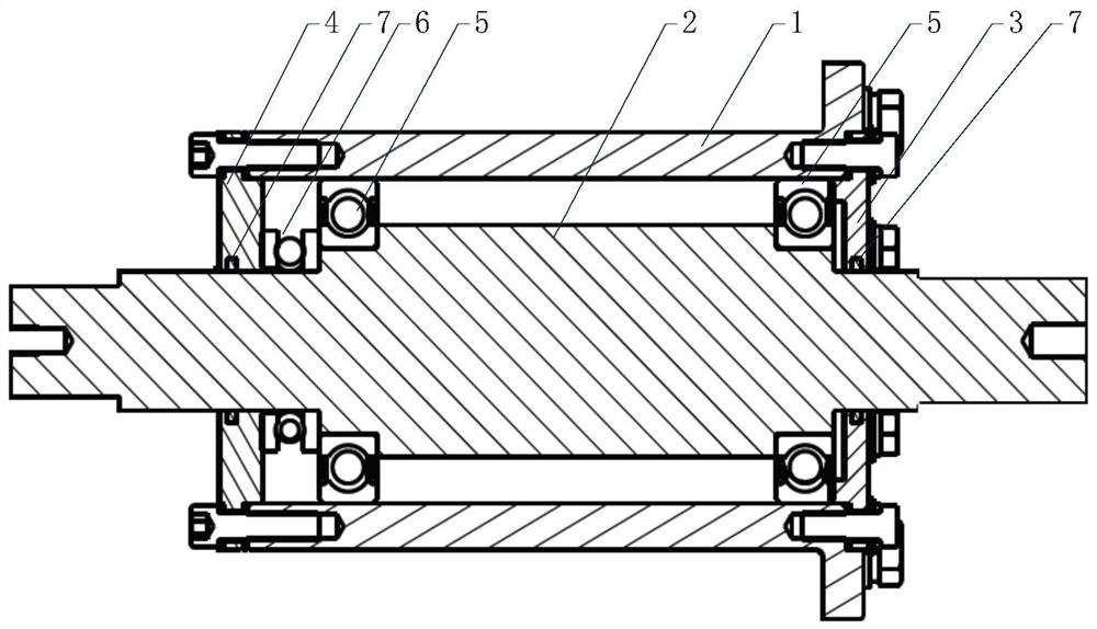
[0049]The transmission mechanism 100 includes a transmission shaft sleeve 1 and a transmission central shaft 2. The transmission shaft sleeve 1 is arranged outside the transmission central shaft 2, and both ends of the transmission central shaft 2 protrude from the transmission shaft sleeve 1. An upper flange cover 3 and a lower flange cover 4 are respectively provided between the transmission shaft sleeve 1 and the transmission center shaft 2 at both ends. The transmission shaft sleeve 1 and the frame 300 are detachably connected. Preferably, the transmission shaft The outer wall of the upper end of the sleeve 1 extends radially outward to form an annular convex edge, and the annular convex edge is connected with the transmission mechanism mounting plate 8 ...

Embodiment 2

[0061] This embodiment is based on Embodiment 1, and the difference from Embodiment 1 is:

[0062] The explosion-proof motor is replaced by an air motor, and the rotation speed of the air motor is controlled by an explosion-proof proportional pressure reducing valve, which is suitable for dense filling of energetic materials with high danger level and strong destructiveness.

Embodiment 3

[0064] This embodiment is based on Embodiment 1, and the inner side walls of the upper flange cover 3 and the lower flange cover 4 are both provided with a rotary sealing ring 7 .


PUM


Abstract

The invention discloses an energetic material filling device. The energetic material filling device comprises a driving mechanism, a transmission mechanism, an eccentric block, a buffer column, a filling platform and a rack, the transmission mechanism is mounted on the rack and comprises a transmission center shaft which is vertically arranged, the bottom of the transmission center shaft is connected with the driving mechanism, and an eccentric block is arranged at the top of the transmission center shaft; the filling platform is connected with the eccentric block, and the filling platform is used for placing packing materials; the buffer column is installed on the rack and arranged on the outer side of the filling platform, and the buffer column can collide with the filling platform in the process that the filling platform eccentrically rotates along with the eccentric block. The device can achieve continuous, efficient and dense filling, is ingenious in structure and reasonable in design, can achieve continuous, safe and efficient dense filling of energetic materials, effectively reduces potential safety hazards in the filling process, and improves the charging quality and productivity of products.

Description

technical field [0001] The invention relates to the technical field of energetic material packaging, in particular to an energetic material filling device. Background technique [0002] At present, in the field of energetic material packaging and warhead charging, in the process of compact packaging and dense filling / charging of energetic materials, there are many technological processes involved, the filling is difficult, the quality of charging is defective, and the filling process There are huge safety hazards. How to reasonably combine various technological processes to improve the quality of charge and packing density, and further reduce the hidden safety hazards of the charge and filling process has become an urgent need of various military units. [0003] In the prior art, there are collision extrusion and electrostatic accumulation in the process of filling and charging, and the adaptability of the equipment is limited, which leads to problems such as defective charg...

Claims


Application Information

Patent Timeline
IPC IPC(8): B65G65/32B65G69/02
CPCB65G65/32B65G69/02
Inventor 朱强王洋齐铭陈金山李瑶瑶李威马涛马新安
Owner 中国兵器装备集团自动化研究所有限公司
Features
  • R&D
  • Intellectual Property
  • Life Sciences
  • Materials
  • Tech Scout
  • Unparalleled Data Quality
  • Higher Quality Content
  • 60% Fewer Hallucinations
Learn More