
Instrument door mechanism of push-pull type distribution box and power distribution box

A power distribution box and distribution box technology, which is applied to the cooling/ventilation of substation/switchgear, electrical components, substation/switch layout details, etc., which can solve the inconvenience of inspection and maintenance of distribution box equipment, inconvenient arrangement, and staggered confusion and other problems, so as to avoid the difficulty of turning over the instrument door, easy maintenance, and orderly connection of lines

Inactive Publication Date: 2022-07-12
SHENZHEN HUATONG ELECTRICAL EQUIP CO LTD
View PDF0 Cites 0 Cited by
  • Summary
  • Abstract
  • Description
  • Claims
  • Application Information

AI Technical Summary

Problems solved by technology

[0002] The distribution box is generally installed outdoors. When the instrument door of the distribution box is opened, the opening space needs to be large, and the general instrument door is a side-turning push-pull type. Once there is an obstruction around it, it will lead to opening The closing angle is small, or it is not easy to open, which makes it inconvenient to check and maintain the internal equipment of the distribution box, and there are many instruments in the distribution box that need to be connected by lines, so there are many internal cables, which is inconvenient to organize and easy to stagger and mess. How inconvenient it is to differentiate

Method used


Image

  • Instrument door mechanism of push-pull type distribution box and power distribution box
  • Instrument door mechanism of push-pull type distribution box and power distribution box
  • Instrument door mechanism of push-pull type distribution box and power distribution box

Examples


Embodiment Construction

[0028] In order to make the objectives, technical solutions and advantages of the present invention clearer, the present invention will be further described in detail below with reference to the accompanying drawings and embodiments. It should be understood that the specific embodiments described herein are only used to explain the present invention, but not to limit the present invention.

[0029] The specific implementation of the present invention will be described in detail below with reference to specific embodiments.

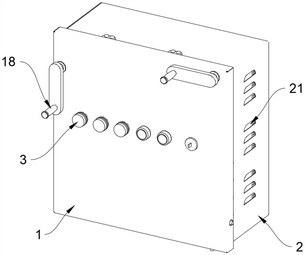
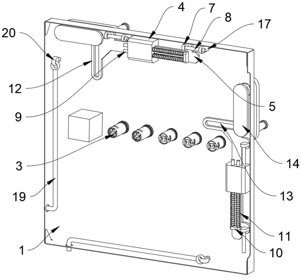
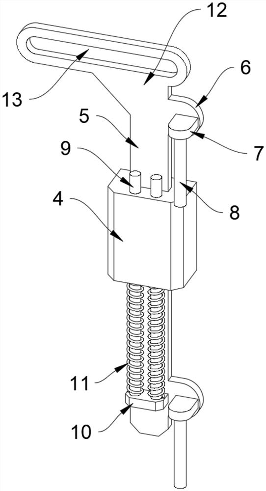
[0030] see Figure 1 to Figure 4 , an instrument door mechanism of a push-pull distribution box, the instrument door mechanism of the push-pull distribution box includes: an instrument door body 1, an indicator light 3, a positioning block 4, an adjustment piece 5, a raised part 6, a basic block 7. The plug-in rod 8, the limit rod 9, the receiving block 10, the first spring 11, the connecting part 12, the connecting piece 14, the sliding block 15 and the ...


PUM


Abstract

The invention relates to the field of power distribution boxes, in particular to an instrument door mechanism of a push-pull type distribution box and the power distribution box. The instrument door mechanism of the push-pull type distribution box comprises an instrument door body, indicator lamps, a positioning block, an adjusting piece, a protruding part, a basic block, an inserting rod, a limiting rod, a bearing block, a first spring, a connecting part, a connecting piece, a sliding block and a rotating rod, and the indicator lamps are embedded in the instrument door body at equal intervals; and positioning blocks are fixedly connected to the top and one side of the inner wall of the instrument door body. According to the instrument door mechanism of the push-pull type distribution box and the power distribution box provided by the invention, the instrument door device is arranged on the power distribution box, so that the opening and closing of the instrument door are facilitated, the instrument door can be adjusted to turn upwards or laterally according to different requirements, and the problem that the instrument door is difficult to turn over due to the shielding of foreign objects is avoided; and through the wire arrangement mechanism, lines in the distribution box are connected more regularly, so that the distribution box is easier and more convenient to maintain.

Description

technical field [0001] The invention relates to the field of power distribution boxes, in particular to an instrument door mechanism of a push-pull type distribution box and a power distribution box. Background technique [0002] The distribution box is generally installed outdoors. When the instrument door of the distribution box is opened, the opening space is required to be large, and the general instrument door is a side-turning push-pull type. Once there are obstacles around, it will lead to opening. The closing angle is small, or it is not easy to open, which makes it inconvenient to inspect and maintain the internal equipment of the distribution box, and there are many kinds of instruments in the distribution box that need to be connected by lines, so there are many cables inside, which is inconvenient to arrange, and it is easy to be staggered and confused. It is inconvenient to distinguish. [0003] Therefore, it is necessary to provide a new push-pull type distrib...

Claims


Application Information

Patent Timeline
Patent Type & Authority Applications(China)
IPC IPC(8): H02B1/20H02B1/56H02B1/46
CPCH02B1/20H02B1/56H02B1/46Y02A30/14
Inventor 吴仙丽吴永恒刘东亮赵发生李亮
Owner SHENZHEN HUATONG ELECTRICAL EQUIP CO LTD
Learn More