Double-cylinder electric nail fixing device

A double-cylinder, electric technology, applied in the direction of nailing tools, staple nailing tools, manufacturing tools, etc., can solve the problems of unstable nailing effect, difficulty in realizing the limit of the firing pin, small volume of the small cylinder, etc. The process of reset and pressurized energy storage is stable, the control method is simple and effective, and the effect of prolonging the gas supply cycle

Active Publication Date: 2022-07-15
SICHUAN UNIVERSITY OF SCIENCE AND ENGINEERING +2
View PDF12 Cites 0 Cited by
  • Summary
  • Abstract
  • Description
  • Claims
  • Application Information

AI Technical Summary

Problems solved by technology

However, due to the small volume of the small tank itself, the power adjustable range is small
In addition, this adjustment action is not precisely controlled by the control system, making the power adjustment inaccurate
[0010] 4. The nail fixer still does not solve the problem of accurate automatic compensation after the gas micro-leakage in the cylinder
When the pressure in the cylinder is high, it is difficult for the crank rocker to store energy
However, only one steel ball in the unilateral blocking structure will be difficult to achieve the limit of the firing pin, and the limiting ability of the unilateral blocking structure to the firing pin depends on the spring performance, the shape of the steel ball and the coefficient of friction. During use, these The parameters will change, which will also make the limit ability of the unilateral blocking structure unstable, and then the nailing effect will be unstable.

Method used


Image

  • Double-cylinder electric nail fixing device
  • Double-cylinder electric nail fixing device
  • Double-cylinder electric nail fixing device

Examples


Embodiment 1

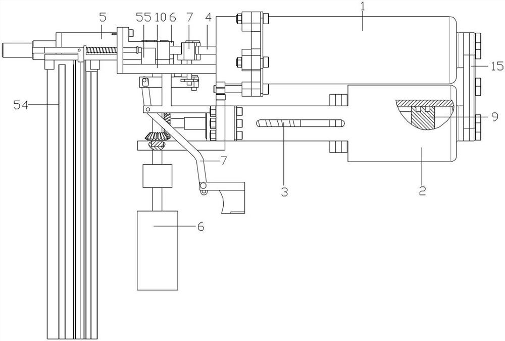
[0067] As a basic embodiment of the present invention, the present invention discloses a double-cylinder electric nail fixer, such as Figure 1-3 As shown, the stapler includes a main cylinder 1 , a secondary cylinder 2 , a linear motion mechanism 3 , a firing needle 4 , a needle tube assembly 5 , a drive mechanism 6 and a limit release mechanism 7 . Taking the direction shown as an example, the left end of the master cylinder 1 and the left end of the sub cylinder 2 are set as the front end, and the right end of the master cylinder 1 and the right end of the sub cylinder 2 are set as the rear end. Among them, the structure, position and connection relationship of each component are as follows:

[0068] The main cylinder 1 is fixedly connected with the auxiliary cylinder 2 , and preferably, the fixed main cylinder 1 is located directly above the auxiliary cylinder 2 . The main cylinder 1 and the auxiliary cylinder 2 are respectively provided with the main piston 8 and the aux...

Embodiment 2

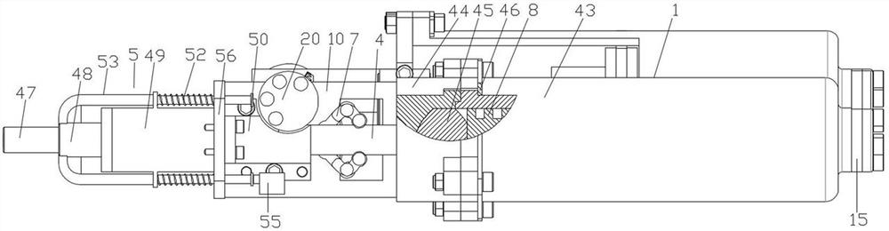
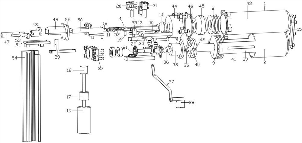
[0076] As a preferred embodiment of the present invention, on the basis of Embodiment 1, this embodiment further improves the master cylinder 1 . like Figure 2-3 As shown, the master cylinder 1 includes a cylinder block 43, a cylinder head 44, a damping pad 45 and a washer 46, the cylinder head 44 is sealed and fixed on the cylinder block 43 by bolts, and the washer 46 is provided with bolt holes around it, and the washer 46 It is fixed between the cylinder head 44 and the cylinder block 43 by bolts and bolt holes, and the shock absorbing pad 45 is fixed in the cylinder head 44 to reduce vibration during the use of the injection gun. The cylinder head 44 has a certain internal space. In order to improve the damping effect, it is preferable that the size and shape of the damping pad 45 are adapted to the internal space of the cylinder head 44, even if the internal space of the cylinder head 44 is completely covered by the damping pad Seat 45 is filled.

Embodiment 3

[0078] As another preferred embodiment of the present invention, on the basis of Embodiment 1, this embodiment further improves the needle tube assembly 5 . like Figure 1-3 As shown, the needle tube assembly 5 includes a needle tube 47 , a needle tube cover 48 , a firing needle guide cover 49 , a firing needle guide seat 50 , a bottom plate 51 and an elastic reset member 52 . The firing pin guide cover 49 has a semicircular structure, the rear end of which is fixed with a fixing plate 56 that is fixedly connected with the connecting piece 10 , and the bottom surface is flat, and a groove is formed on the flat surface. The main body of the firing pin guide seat 50 is a square structure, its bottom surface is provided with a firing channel for the firing pin 4 to move, its front end is matched with the groove on the firing pin guide cover 49, and its rear end and the upper part of the middle part are provided with fixed Structure, the front end of the firing pin guide seat 50 ...


PUM


Abstract

The invention discloses a double-air-cylinder electric nail fixing device which comprises a main air cylinder, an auxiliary air cylinder, a linear motion mechanism, a firing pin, a needle tube assembly, a driving mechanism and a limiting releasing mechanism. The main air cylinder is fixedly connected with the auxiliary air cylinder, and an inner cavity of the main air cylinder is communicated with an inner cavity of the auxiliary air cylinder; a main piston and an auxiliary piston are arranged in the main air cylinder and the auxiliary air cylinder respectively, the needle tube assembly is fixedly connected with the main air cylinder through a connecting piece, one end of the firing pin is movably arranged in the needle tube assembly, and the other end of the firing pin is fixedly connected with the main piston. The limiting and releasing mechanism used for limiting or releasing the firing pin is arranged beside the firing pin, the linear motion mechanism is fixedly connected with the auxiliary piston, and the driving mechanism is connected with the firing pin and the linear motion mechanism. Compression of high-pressure gas in the cylinder can be achieved under the condition that the bearing capacity is small, and the micro leakage amount of the gas in the cylinder can be automatically compensated and the nailing power can be automatically adjusted by adjusting the stroke of the driving mechanism.

Description

technical field [0001] The invention belongs to the technical field of fastening, and in particular relates to a double-cylinder electric nail fixer. Background technique [0002] Existing electric nail fixers are mainly divided into single-cylinder and double-cylinder structures. For the single-cylinder nail fixer, it mainly realizes the nail-fixing action by presetting high-pressure gas with different energy in the cylinder, but the single-cylinder nail fixer has the following technical problems in practical application: [0003] First, the single-cylinder nail fixer adopts gear transmission for high-pressure gas compression, and the transmission system has a large load and is prone to failure, so that the single-cylinder nail fixer has not been able to break through the bottleneck of high-power nail fixation. Second, the parameters of the single-cylinder nail fixer are fixed, and it does not have the function of adjusting the power of nailing. Third, the single-cylinder...

Claims


Application Information

Patent Timeline
Patent Type & Authority Applications(China)
IPC IPC(8): B25C1/04B25C7/00
CPCB25C1/04B25C7/00
Inventor 文华斌李彪陶静刘杰何平杨余李正东
Owner SICHUAN UNIVERSITY OF SCIENCE AND ENGINEERING
Why Eureka
Try Eureka