Indoor energy-saving LED display screen and use method thereof

An LED display screen, energy-saving technology, applied in the field of display screen, can solve the problems of cumbersome adjustment work, structure curing, etc., to achieve the effect of flexible space occupation position, avoid cumbersome process, avoid unnecessary loss

Pending Publication Date: 2022-07-15
深圳市鸿茂元智光电有限公司
View PDF0 Cites 0 Cited by
  • Summary
  • Abstract
  • Description
  • Claims
  • Application Information

AI Technical Summary

Problems solved by technology

[0002] The display screen is a professional device used to convert and display data, output pictures, text or video, and facilitate user identification. The principle of the LED display screen is to use multiple LED display modules to form a screen for display work. In the actual use of the display screen, since the assembly method of the display screen is often fixed by a single b

Method used


Image

  • Indoor energy-saving LED display screen and use method thereof
  • Indoor energy-saving LED display screen and use method thereof
  • Indoor energy-saving LED display screen and use method thereof

Examples


Embodiment 1

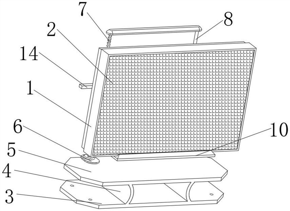
[0034] see Figure 1-4 , the present invention provides a technical solution: an indoor energy-saving LED display screen, comprising a casing 1, the inner front of the casing 1 is equipped with a screen 2, and the display function of the display screen can be realized through the screen 2, and the display function of the casing 1 can be realized. The bottom surface is provided with a bottom plate 3, the upper surface of the bottom plate 3 is provided with a support plate 4 on both sides, the upper surface of the support plate 4 is provided with a support plate 5, and the rear end of the support plate 5 is equipped with a No. Provide stable support for the operation of No. 1 motor 6. The shape of the support plate 4 is arc. The purpose of this design is to provide the support plate 5 with a space for force buffering through the arc shape of the support plate 4, so that the support plate The structure of 5 is more stable. The four corners of the upper surface of the base plate 3...

Embodiment 2

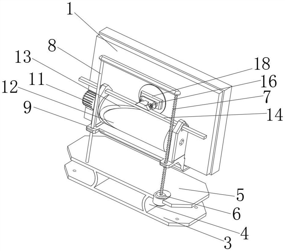
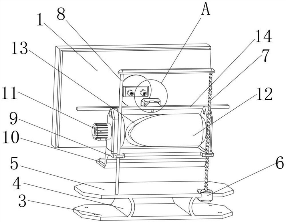
[0037] see Figure 3-4 , the connecting mechanism includes a connecting frame 16, a connecting plate 17 and a rear end frame 18, the connecting frame 16 is installed at the center position of the front end of the guide rod 14, the connecting plate 17 is fixedly connected with the connecting frame 16, and the rear end frame 18 is installed in the housing 1. The center position of the rear end. The purpose of this design is to realize the position fixing function of the rear end frame 18 and the connecting plate 17. Both sides of the rear end of the rear end frame 18 are equipped with pressure rods 19, and the rear end of the pressure rod 19 is equipped with a pressure rod 19. Insertion rod 20, both sides of the rear end of the connecting plate 17 are provided with jacks 21, the inserting rod 20 is inserted in the inner side of the jacking hole 21, the pressing rod 19 is fitted with the connecting plate 17, and the inserting rod 20 is inserted into the jacking hole 21 The inner ...

Embodiment 3

[0039] see Figure 5-6 , the inner side of the casing 1 is equipped with a circuit board 23, the circuit board 23 is electrically connected with the screen 2, and the display content of the screen 2 can be controlled through the circuit board 23, the inner and lower surface of the casing 1 is equipped with a water collecting tank 24, which collects The inner side of the water tank 24 is filled with the cooling liquid. The purpose of this design is to realize the filling function of the cooling liquid. The other end of 25 is equipped with a cooling pipe 27, and one end of the cooling pipe 27 is equipped with a return pipe 28. Both the suction pipe 26 and the return pipe 28 are inserted into the inner side of the water collecting tank 24. The purpose of this design is to construct the circulation of the cooling liquid. The self-circulation function of the cooling liquid is realized by the suction pump 25. The upper surface of the water collecting tank 24 is equipped with a place...


PUM


Abstract

The invention provides an indoor energy-saving LED display screen and a using method thereof, and relates to the technical field of display screens, the indoor energy-saving LED display screen comprises a shell, a screen is installed at the front end of the inner side of the shell, a bottom plate is arranged on the lower surface of the shell, supporting plates are installed on the two sides of the upper surface of the bottom plate, supporting plates are installed on the upper surfaces of the supporting plates, and first motors are installed at the rear ends of the supporting plates. According to the device, the first motor, the screw rod, the limiting rod, the supporting frame, the supporting plate, the second motor, a roller, a sliding groove, a guide rod and a driving rod are arranged, the height adjusting function of the supporting frame can be achieved through structural combination of the first motor, the screw rod, the limiting rod and the supporting frame, then the height of a screen is adjusted, and the height of the screen is adjusted through the second motor, the roller, the sliding groove, the guide rod and the driving rod. The left-right adjusting function of the guide rod is achieved, and then the left-right position of the screen is adjusted, so that after the display screen is assembled, the position of the screen is freely adjusted, the watching experience of a user is ensured, and meanwhile the occupied space is more flexible.

Description

technical field [0001] The invention relates to the technical field of display screens, in particular to an indoor energy-saving LED display screen and a method for using the same. Background technique [0002] The display screen is a professional device used to convert and display data, output pictures, text or video, and facilitate user identification. The principle of the LED display screen is to form a screen through multiple LED display modules for display work. In the actual use of the display screen, because the assembly method of the display screen is often fixed by a single bracket, its structure is relatively solid. After the assembly is completed, the later adjustment work is more complicated, and in the indoor environment, it is often necessary to adjust according to other indoor appliances. The position of the display screen is adjusted by changing the position of the display screen. This solidified assembly structure has an impact on the later adjustment of the...

Claims


Application Information

Patent Timeline
IPC IPC(8): F16M13/02F16M11/04F16M11/18
CPCF16M13/02F16M11/045F16M11/046F16M11/18
Inventor 栾先铭马晓琴马世超刘欣欣
Owner 深圳市鸿茂元智光电有限公司
Why Eureka
Try Eureka