Small-range opening type fresh food cabinet
An open-type, fresh-keeping cabinet technology
- Summary
- Abstract
- Description
- Claims
- Application Information
AI Technical Summary
Problems solved by technology
Method used
Image
Examples
Embodiment 1
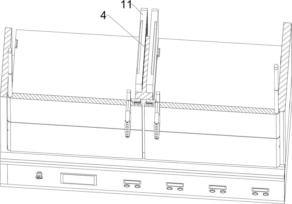
[0035] A small-scale open fresh food cabinet includes a base 1, a cabinet body 2, a transparent cabinet door 3, a partition 4, a rotating shaft 6, a drive mechanism 7 and a placement mechanism 8, please refer to figure 1 , figure 2 , image 3 , Figure 4 , Figure 5 , Figure 9 , Figure 11 and Figure 12 As shown in the figure, the top of the base 1 is installed with the cabinet 2 by means of bolts, and the partition plate 4 is installed between the middle of the inner top and the inner bottom of the cabinet 2 by bolts. There is a rotating shaft 6 in a left-right symmetrical rotating connection between the sides, and three transparent cabinet doors 3 are set on the rotating shaft 6. The inner side of the rear side of the transparent cabinet door 3 is in contact with the front side of the partition 4, and the bottom of the transparent cabinet door 3 on the upper and lower sides is in contact with each other. There are card slots 5 on the inside, and a drive mechanism 7 ...
Embodiment 2
[0042] On the basis of Embodiment 1, a clamping mechanism 9 is also included. The clamping mechanism 9 includes a sliding rod 92, a contact wheel 93, a guide frame 94, a vertical plate 95, a second spring 96 and a clamping rod 97. Please refer to figure 2 , image 3 , Figure 4 and Image 6 As shown, limit slots 98 are symmetrically opened on the inner sides of the rotating shafts 6 on the left and right sides, and guide grooves 91 are opened on the inner sides of the outer sides of the transparent cabinet doors 3 on the upper and lower sides. The side of 94 away from the rotating shaft 6 has a character hole, and the outer end of the guide frame 94 is installed with a clamping rod 97 by means of bolt connection. For fixing, vertical plates 95 are fixed at the position where the inner bottom of the lower guide frame 94 is far away from the rotating shaft 6 and the position where the inner top of the upper guide frame 94 is far away from the rotating shaft 6. A second sprin...
Embodiment 3
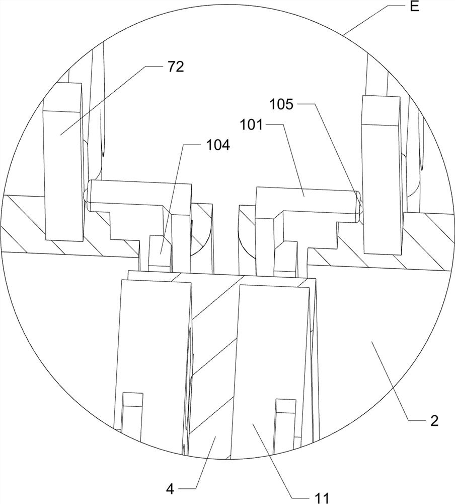
[0047] On the basis of Embodiment 1 and Embodiment 2, a multi-slotted plate 11 and a rotating rod 12 are also included. Please refer to figure 2 , Figure 10 and Figure 11 As shown in the figure, a rotating rod 12 is embedded in the lower part of the left and right sides of the partition plate 4, and the middle part of the rotating rod 12 is installed with a multi-slot plate 11 by means of bolts. The operator can place the eggs on the multi-slot plate 11 .
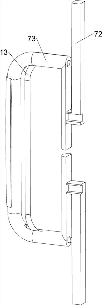
[0048] Also includes u-bar 13 and fourth spring 14, see Figure 7-Figure 9 As shown, a groove 15 is symmetrically opened on the front side of the middle transparent cabinet door 3 close to the handle 73, and a u-shaped rod 13 is slidably connected between the upper and lower sides of the handle 73, and the rear end of the u-shaped rod 13 is located in the groove. In the groove 15 , the u-shaped rod 13 can limit the handle 73 . A fourth spring 14 is installed symmetrically up and down on the outer front side of the u-s...
PUM
 Abstract
Description
Claims
Application Information
 - R&D
- Intellectual Property
- Life Sciences
- Materials
- Tech Scout
- Unparalleled Data Quality
- Higher Quality Content
- 60% Fewer Hallucinations
Browse by: Latest US Patents, China's latest patents, Technical Efficacy Thesaurus, Application Domain, Technology Topic, Popular Technical Reports.
© 2025 PatSnap. All rights reserved.Legal|Privacy policy|Modern Slavery Act Transparency Statement|Sitemap|About US| Contact US: help@patsnap.com


