Deformable variable-frequency sound absorption device

A technology of sound-absorbing devices and cavities, which is applied in sound-generating devices, additive processing, instruments, etc., can solve the problems of low service life of porous foam, difficulty in frequency conversion and noise reduction, and small range of frequency band changes, achieving excellent surface quality, Effect of reducing stress concentration and improving overall firmness

Pending Publication Date: 2022-07-15
HUAZHONG UNIV OF SCI & TECH
View PDF0 Cites 0 Cited by
  • Summary
  • Abstract
  • Description
  • Claims
  • Application Information

AI Technical Summary

Problems solved by technology

In the past, scientific researchers realized the effect of sound absorption and noise reduction by designing a porous foam structure on the periphery of the space. This method can achieve sound wave noise reduction in a specified frequency band, but it is difficult to achieve frequency conversion noise reduction in complex and changeable sound wave scenes, and porous foam also There are disadvantages of low service life
[0003] In order to solve the above defects, a sound-absorbing lattice structure of metal panels has appeared. However, this method only improves the service life, and it is difficult to achieve the effect of frequency conversion and noise reduction. The change of porosity can achieve the effect of frequency conversion and noise reduction, but the range of frequency band change is small, so it is difficult to experiment with effective frequency conversion sound absorption

Method used


Image

  • Deformable variable-frequency sound absorption device
  • Deformable variable-frequency sound absorption device
  • Deformable variable-frequency sound absorption device

Examples


specific Embodiment

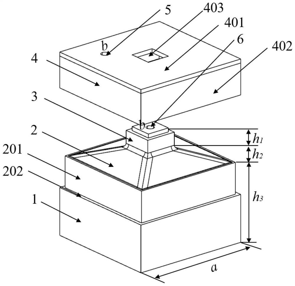
[0054] The deformable frequency conversion sound absorption structure is designed by CAD software. The bottom cavity structure and the support part are cubes, that is, the bottom surface of the bottom cavity structure and the support part are square, the length and width of the bottom cavity structure are 30mm, and the height of the support part is h 1 =4mm, the height of the camber bulge h 2 =3mm, bottom cavity height h 3 = 20mm, the length and width of the support are 8mm, the length and width of the boss of the support part are 7mm, and the height is 1mm.

[0055] The thickness of the bottom cavity structure is 1mm, the wall thickness of the convex arc surface is 0.5mm, the wall thickness of the support part is 1mm, the length and width of the inner wall of the side wall of the top cover are both 29mm, and the thickness is 0.5mm. The length and width of the bottom cavity boss are equal to the length and width of the inner wall of the side wall of the top cover, and the hei...


PUM


Abstract

The invention discloses a sound absorption device capable of deforming and converting frequency. The sound absorption device comprises a top cover and a cavity body, the cavity body comprises a bottom-layer cavity structure and a supporting part, the supporting part is arranged at the top of the bottom-layer cavity structure, the bottom-layer cavity structure is communicated with the outside through a through hole, the top cover comprises a top plate and a top cover side wall, the top plate is connected with the supporting part, the top cover, the top cover side wall and the top surface of the bottom-layer cavity structure form an upper-layer cavity, and the upper-layer cavity is communicated with the outside through a through hole; the inner surface of the top cover side wall makes contact with the outer surface of the side wall of the bottom layer cavity structure. The top face, connected with the supporting part, of the bottom layer cavity structure is a protruding arc face, when the top cover is subjected to external force in the direction towards the bottom layer cavity structure, the side wall of the top cover can slide on the side wall of the bottom layer cavity structure, the protruding arc face deforms and concaves downwards, the sound absorption frequency is changed, and the sound absorption device material has the shape memory effect. The size of the cavity can be controllably changed through deformation and controllable recovery of the sound absorption device, and repeatable frequency conversion and noise reduction can be effectively achieved.

Description

technical field [0001] The invention belongs to the technical field of sound absorption, and more particularly, relates to a sound absorption device with deformable frequency conversion. Background technique [0002] With the development of modern society, multi-band noise also comes along, which seriously affects the normal life of human beings. In the past, scientific researchers achieved the effect of sound absorption and noise reduction by designing a porous foam structure at the periphery of the space. This method can achieve sound wave noise reduction in a specified frequency band, but it is difficult to achieve variable frequency noise reduction in complex and changeable sound wave scenes. There is a disadvantage of low service life. [0003] In order to solve the above defects, a metal plate lattice sound-absorbing lattice structure appears. However, this method only improves the service life, and it is difficult to achieve the effect of frequency conversion and noi...

Claims


Application Information

Patent Timeline
Patent Type & Authority Applications(China)
IPC IPC(8): G10K11/162G10K11/175B33Y80/00
CPCG10K11/162G10K11/1752B33Y80/00
Inventor 宋波张志范军翔史玉升
Owner HUAZHONG UNIV OF SCI & TECH
Why Eureka
Try Eureka