
Combustion chamber mixing structure based on bluff body group

A technology of combustion chamber and blunt body, which is applied in the direction of combustion chamber, continuous combustion chamber, combustion method, etc., can solve the problems of unstable combustion, affecting the working stability of gas turbine, insufficient fuel combustion, etc., and achieve the purpose of improving the mixing effect of oil and gas Effect

Pending Publication Date: 2022-07-22
HARBIN ENG UNIV
View PDF12 Cites 0 Cited by
  • Summary
  • Abstract
  • Description
  • Claims
  • Application Information

AI Technical Summary

Problems solved by technology

However, there are problems of insufficient fuel combustion and unstable combustion in the combustion chamber, which greatly affects the working stability of the gas turbine. Therefore, it is necessary to design a structure that can improve the effect of oil-gas mixing and stabilize the flame.

Method used


Image

  • Combustion chamber mixing structure based on bluff body group
  • Combustion chamber mixing structure based on bluff body group
  • Combustion chamber mixing structure based on bluff body group

Examples


Embodiment Construction

[0017] The present invention will be described in more detail below in conjunction with the accompanying drawings:

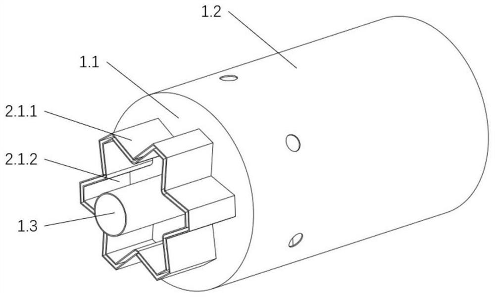
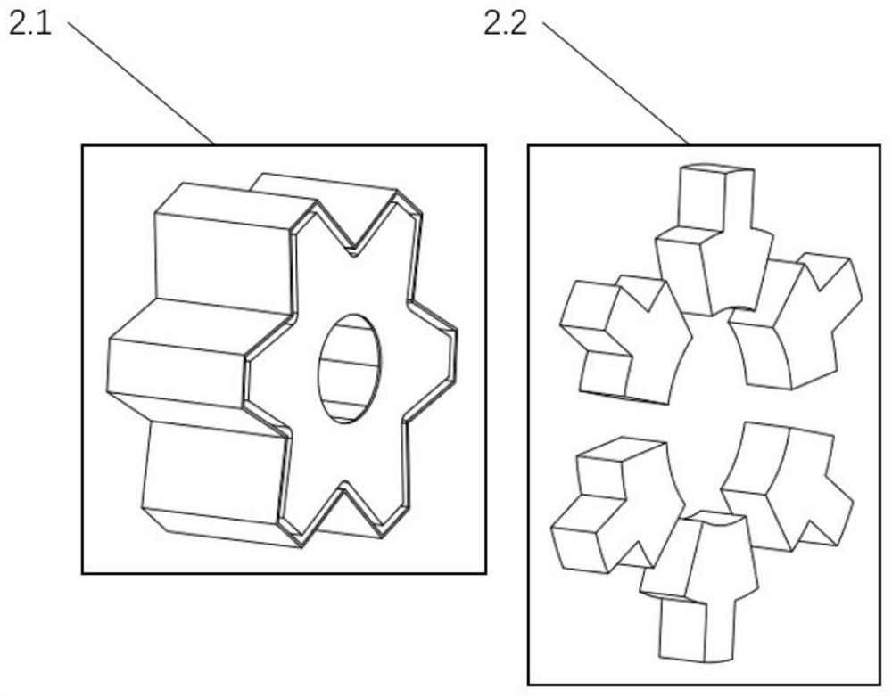
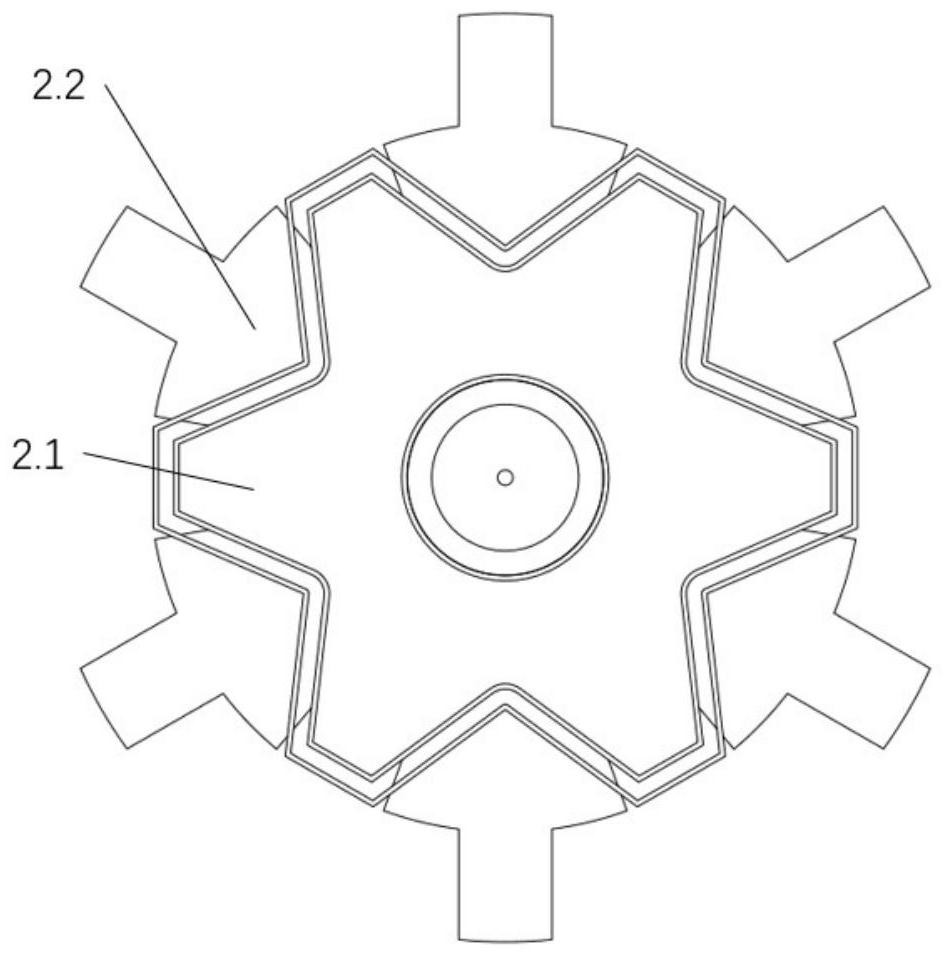
[0018] combine Figure 1-7 , the present invention includes: a combustion chamber 1 and a bluff body group 2 . The combustion chamber includes a front wall 1.1, a pipe wall 1.2, and a nozzle 1.3; the bluff body group 2 includes a front bluff body 2.1 and a rear bluff body 2.2.

[0019] The front bluff body 2.1 is composed of an outer wall 2.1.1 and an inner wall 2.1.2, and a flow channel is formed between the outer wall 2.1.1 and the inner wall 2.1.2.

[0020] The front bluff body 2.1 adopts a trapezoidal cross-section, which is fixed on the front wall 1.1 of the combustion chamber 1, and 6 are evenly arranged in the circumferential direction; the trapezoidal cross-section can ensure the stable feeding of the pipe wall 1.2 side while generating the front bluff body 2.1 and the rear detachment vortex. gas.

[0021] The rear bluff body 2.2 is fixed on the tube ...


PUM


Abstract

The combustion chamber mixing structure based on the bluff body set comprises a combustion chamber and the bluff body set, the combustion chamber comprises a front wall and a pipe wall behind the front wall, a nozzle is installed on the front wall, the bluff body set comprises a front bluff body and a rear bluff body, the front bluff body comprises an outer wall and an inner wall, the inner wall is located outside the nozzle, the outer wall is located outside the inner wall, and the inner wall is located outside the rear bluff body. A flow channel is formed between the outer wall and the inner wall and communicated with the inner space of the pipe wall, an air inlet is formed in the pipe wall, and a rear bluff body is arranged behind the air inlet. The multiple pairs of bluff body sets are additionally arranged on the basis of a traditional combustion chamber, a swirler can be replaced, the oil and gas mixing effect is improved, and meanwhile the flame stabilizing effect is achieved.

Description

technical field [0001] The present invention relates to a gas turbine, in particular to a combustion chamber structure of the gas turbine. Background technique [0002] Gas turbine has the characteristics of high power density and strong maneuverability. Its main components include compressor, combustion chamber, and turbine. It is a typical power plant. The compressor does work on the incoming gas to increase the pressure, and the fuel is ignited in the combustion chamber and mixed with the incoming high-pressure gas to drive the turbine to do work, and the work generated by the turbine is used to drive the compressor to rotate, forming a Brayton cycle. However, there are problems of insufficient fuel combustion and unstable combustion in the combustion chamber, which greatly affects the working stability of the gas turbine. Therefore, it is necessary to design a structure that can improve the mixing effect of oil and gas and stabilize the flame. SUMMARY OF THE INVENTION ...

Claims


Application Information

Patent Timeline
Patent Type & Authority Applications(China)
IPC IPC(8): F23R3/18F23R3/28
CPCF23R3/18F23R3/286
Inventor 王忠义李政王瑞浩宋天楚王艳华王萌万雷王松
Owner HARBIN ENG UNIV
Learn More