Joint angle monitoring device and method and readable storage medium
A technology for monitoring device and joint angle, which is applied in diagnostic recording/measurement, medical science, diagnosis, etc. It can solve problems such as low accuracy, monitoring position, high requirements for wearing methods, and poor comfort, and achieve real-time monitoring.
- Summary
- Abstract
- Description
- Claims
- Application Information
AI Technical Summary
Problems solved by technology
Method used
Image

Examples
Embodiment 1
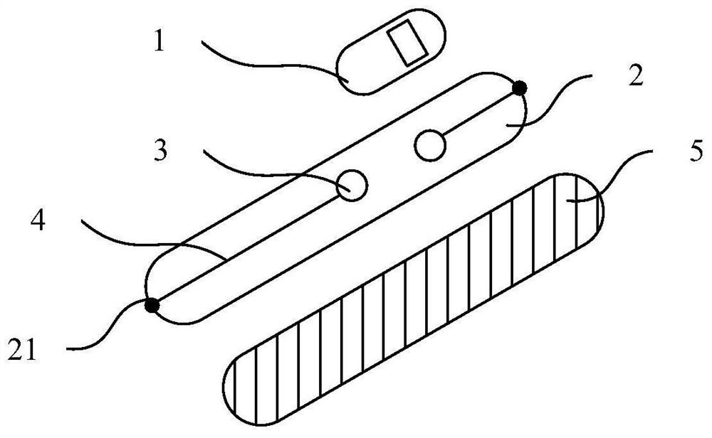
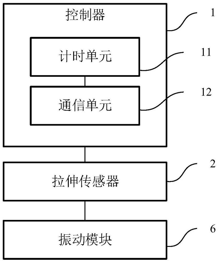
[0051] A joint angle monitoring device, such as Figure 1-2 As shown, the monitoring device includes a controller 1 and a tensile sensor 2;
[0052] The stretch sensor 2 is used to be attached to the joint of the user;
[0053] The attachment object may be any joint that needs to be detected, including but not limited to cervical spine, lumbar spine, elbow, wrist, knee joint, ankle, and the like.
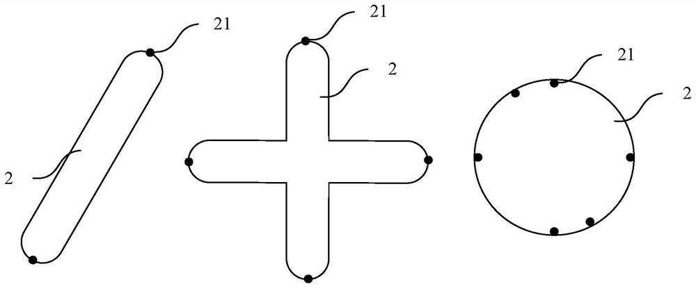
[0054] In this embodiment, in order to ensure the comfort and effectiveness of the attachment, the stretch sensor 2 is a sheet sensor, and the material of the stretch sensor 2 is a cotton fabric conductive composite material, such as polypyrrole (polypyrrole, referred to as Ppy). In addition, the monitoring device of this embodiment further includes a sticker 5 , the sticker 5 and the stretch sensor 2 are pressed as a whole, and the stretch sensor 2 is pasted with the joint through the sticker 5 .
[0055] After the stretch sensor 2 is attached to the joint of the user, the stret...
Embodiment 2
[0079] A joint angle monitoring method, such as Figure 4 As shown, the monitoring method is implemented by using the joint angle monitoring device described in Embodiment 1, and the monitoring method includes:
[0080] Step 10. The stretch sensor acquires stretch data when the joint moves;
[0081] Specifically, the stretch sensor stretches when the joint moves, and acquires a resistance value between each pair of electrodes; the stretch data includes the resistance value;
[0082] Step 20, the controller obtains the joint motion angle corresponding to the stretching data according to the preset correspondence;
[0083] The correspondence is used to represent different joint motion angles corresponding to different stretch data.
[0084] Among them, such as Figure 5 As shown, step 20 specifically includes:
[0085] Step 201, the controller obtains the corresponding stretched length according to the resistance value;
[0086] Step 202, the controller obtains the correspo...
Embodiment 3
[0096] A computer-readable storage medium on which a computer program is stored, and when the program is executed by a processor, implements the steps of the joint angle monitoring method described in Embodiment 2.
[0097] Wherein, the readable storage medium may include, but is not limited to, a portable disk, a hard disk, a random access memory, a read-only memory, an erasable programmable read-only memory, an optical storage device, a magnetic storage device, or any of the above suitable combination.
[0098] In a possible implementation manner, the present invention can also be implemented in the form of a program product, which includes program codes, when the program product runs on a terminal device, the program code is used to cause the terminal device to execute the implementation The steps of the joint angle monitoring method described in Embodiment 2.
[0099] Wherein, the program code for executing the present invention can be written in any combination of one or...
PUM
| Property | Measurement | Unit |
|---|---|---|
| Resistance | aaaaa | aaaaa |
| Resistance | aaaaa | aaaaa |
| Resistance | aaaaa | aaaaa |
Abstract
Description
Claims
Application Information
 - R&D
- Intellectual Property
- Life Sciences
- Materials
- Tech Scout
- Unparalleled Data Quality
- Higher Quality Content
- 60% Fewer Hallucinations
Browse by: Latest US Patents, China's latest patents, Technical Efficacy Thesaurus, Application Domain, Technology Topic, Popular Technical Reports.
© 2025 PatSnap. All rights reserved.Legal|Privacy policy|Modern Slavery Act Transparency Statement|Sitemap|About US| Contact US: help@patsnap.com