Grip displacement testing system and method based on ten-shaft sensor

A shaft sensor and test system technology, which is applied in signal transmission systems, instruments, measuring devices, etc., can solve the problems of no monitoring management and early warning system, inability to accurately capture and transmit strain, and inability to accurately capture small strains, so as to save field Effect of experiment time, enhanced visualization and controllability, and convenient construction technology

Pending Publication Date: 2019-03-12
SHANDONG UNIV +1
View PDF14 Cites 3 Cited by
  • Summary
  • Abstract
  • Description
  • Claims
  • Application Information

AI Technical Summary

Problems solved by technology

[0005] In existing projects, there is a method of binding geogrids and strain sensing fiber gratings together to measure their deformation and force. However, this method is easy to loose due to the binding method. Once loose, it will not be able to accurately capture and transmit strain, resulting in large errors in the obtained data. At the same time, this method is limited by its material, and can only measure large deformations, and small strains cannot be accurately captured. The purpose of taking corresponding measures in a timely manner
[0006] To sum up, for the visual test and prediction of structural damage caused by geological disasters, and there is no overall monitoring management and early warning system for geological disasters after geological disasters damage structures

Method used


Image

  • Grip displacement testing system and method based on ten-shaft sensor
  • Grip displacement testing system and method based on ten-shaft sensor
  • Grip displacement testing system and method based on ten-shaft sensor

Examples


Embodiment 1

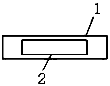
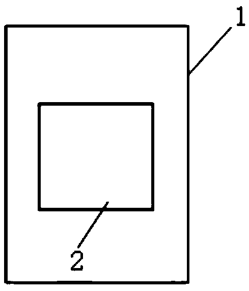
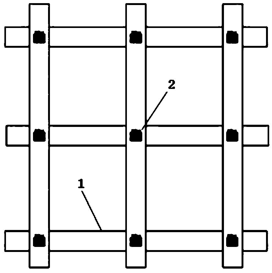
[0069] Grid displacement test system based on ten-axis sensor, including: ten-axis sensor chip, geogrid, management and monitoring cloud platform, monitoring database server, remote monitoring center and mobile client.

[0070] The ten-axis sensor chip is embedded in the geogrid; as figure 1 As shown, it is a side sectional view of a geogrid embedded with a ten-axis sensor of the present disclosure;

[0071] The ten-axis sensor chip collects the data information of acceleration, angle, angular velocity, magnetic field, altitude, air pressure and geographical coordinates of the monitoring point, and uploads the data information to the management monitoring cloud platform;

[0072] The management and monitoring cloud platform obtains the deformation and displacement changes of the geogrid at the monitoring point through comprehensive analysis based on the data information collected by the ten-axis sensor chip, and performs error correction processing on the data information to r...

Embodiment 2

[0119] The method of using the grid displacement test system based on the ten-axis sensor includes the following steps:

[0120] The ten-axis sensor chip collects the data information of acceleration, angle, angular velocity, magnetic field, altitude, air pressure and geographical coordinates of the monitoring point, and uploads the data information to the management monitoring cloud platform;

[0121] The management and monitoring cloud platform obtains the deformation and displacement changes of the geogrid at the monitoring point through comprehensive analysis based on the data information collected by the ten-axis sensor chip, and performs error correction processing on the data information to reduce the data error rate and improve the data integrity rate;

[0122] The management and monitoring cloud platform synchronously updates the data information and analysis results collected by the ten-axis sensor chip to the monitoring database server;

[0123] The remote monitorin...


PUM


Abstract

The invention provides a grid displacement testing system and method based on a ten-shaft sensor. The grid displacement testing method comprises the steps that a ten-shaft sensor chip is embedded intoa geogrid; the ten-shaft sensor chip acquires data information of a monitoring point and uploads the data information to a monitoring cloud management platform; the monitoring cloud management platform obtains geogrid deformation amount and displacement change of the monitoring point through comprehensive analysis according to the acquired data information, conducts error correction processing onthe data information, reduces data error rate and improves data integrity rate; the monitoring cloud management platform synchronously updates the data information acquired by the ten-shaft sensor chip and analysis results to a monitoring database server; a remote monitoring center extracts data in the monitoring database server, obtains the width and extension trend of cracks produced by a wholestructure of the geogrid after further processing, monitors the overall damage trend of the geogrid in real time and finally achieves automatic monitoring of the overall state of the geogrid and early warning of geological disasters.

Description

technical field [0001] The present disclosure relates to the technical field of civil engineering monitoring, in particular to a grid displacement testing system and method based on a ten-axis sensor. Background technique [0002] In recent years, geological disasters have occurred frequently, which have had a great impact on people's lives and safety, not only causing damage to engineering facilities, but also bringing huge economic losses. Therefore, appropriate preventive measures for geological disasters should be taken to minimize geological Minimize the losses caused by disasters. At present, most of the engineering projects focus on strengthening the areas that may be damaged according to the construction experience and engineering practice. Due to the differences in various factors such as topography, geology, and environment, there is a lack of uniform criteria for determining the areas that may be damaged. Factors have a great influence, and judgment bias may occu...

Claims


Application Information

Patent Timeline
Patent Type & Authority Applications(China)
IPC IPC(8): G01D21/02G08C17/02
CPCG08C17/02G01D21/02
Inventor 张炯代朝霞夏霜胡念佘蕊韩若楠崔新壮张齐鲁
Owner SHANDONG UNIV
Why Eureka
Try Eureka