
Efficient gluing equipment for electronic component processing

A technology of electronic components and gluing, which is applied in the direction of coating and liquid coating devices on the surface, can solve the problems of easy damage, low quality and efficiency of gluing, and slow efficiency of gluing methods, so as to improve operating efficiency Effect

Pending Publication Date: 2022-07-26
彭宇航
View PDF1 Cites 0 Cited by
  • Summary
  • Abstract
  • Description
  • Claims
  • Application Information

AI Technical Summary

Problems solved by technology

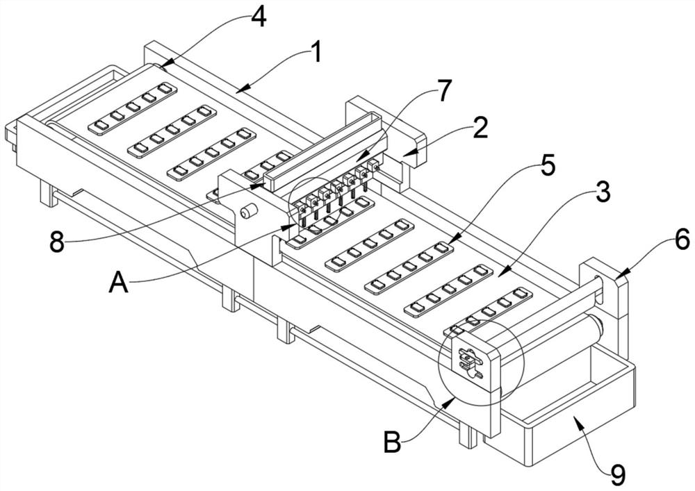
[0003] According to CN202111259489.0, a high-efficiency gluing equipment for processing electronic components is proposed, the purpose of which is to solve the problem: the existing dripper is a single hole, and it is relatively difficult to move the dripper through mechanical equipment when applying glue on a large area. There are many steps, which are time-consuming and labor-intensive, and the quality and efficiency of gluing are low; however, in the existing high-efficiency gluing equipment for electronic components, gluing is performed point-to-point, and the efficiency of this gluing method is slow. It is necessary to use multiple gluing brushes to glue the electronic components at the same time; and the brushes are easily damaged after long-term use, so they need to be disassembled and replaced to ensure work efficiency; Electronic glue is easy to drop on the surface of the hard conveyor belt, so it needs to be scraped
Therefore, it does not meet the existing needs, so we propose a high-efficiency gluing equipment for electronic components processing

Method used


Image

  • Efficient gluing equipment for electronic component processing
  • Efficient gluing equipment for electronic component processing
  • Efficient gluing equipment for electronic component processing

Examples


Embodiment Construction

[0027] The technical solutions in the embodiments of the present invention will be clearly and completely described below with reference to the accompanying drawings in the embodiments of the present invention. Obviously, the described embodiments are only a part of the embodiments of the present invention, but not all of the embodiments.

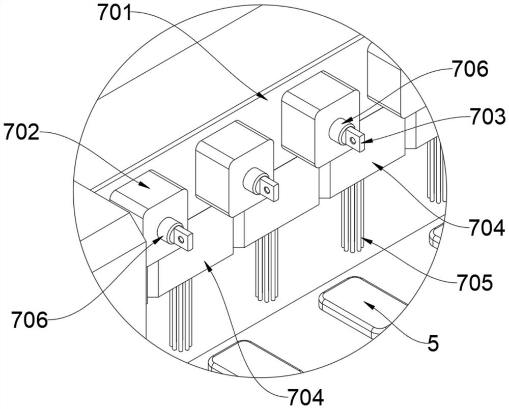
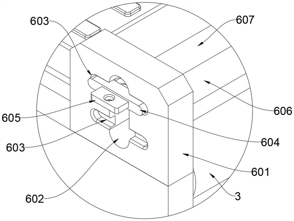
[0028] see Figure 1 to Figure 6 , an embodiment provided by the present invention: a high-efficiency gluing equipment for processing electronic components, comprising two supporting side plates 1, and rolling cylinders 4 are movably provided on both sides between the two supporting side plates 1 , a rigid conveyor belt 3 is movably arranged between the two rolling cylinders 4, a plurality of electronic component fixing plates 5 are placed on the upper surface of the rigid conveyor belt 3, and the front and rear sides of the middle of the upper end of the two supporting side plates 1 are fixed. A T-shaped support plate 2 is provided, a glui...


PUM


Abstract

The invention discloses efficient gluing equipment for processing electronic components, relates to the technical field of efficient gluing equipment, and solves the problem that a brush is very easy to damage after being used for a long time and needs to be detached and replaced to ensure the working efficiency. Efficient gluing equipment for electronic component processing comprises two supporting side plates, rolling cylinders are movably arranged on the two sides between the two supporting side plates, a hard conveying belt is movably arranged between the two rolling cylinders in a matched mode, and a plurality of electronic component fixing plates are placed on the upper surface of the hard conveying belt; t-shaped supporting plates are fixedly arranged on the front sides and the rear sides of the middles of the upper ends of the two supporting side plates correspondingly, and a gluing mechanism is fixedly arranged between the two T-shaped supporting plates. The whole brush is inserted into the insertion type deep groove in the lower end of the matched cross beam, so that the limiting clamping blocks can be inserted into the limiting clamping grooves in the two sides of the insertion type plate.

Description

technical field [0001] The invention relates to the technical field of high-efficiency gluing equipment, in particular to a high-efficiency gluing device used for processing electronic components. Background technique [0002] With the rapid development of society and economy, mechanization, automation and standardized production have gradually become the development trend. Electronic product manufacturers also need to keep pace with the times. Electronic components need electronic components to receive information during production. During the process, it is necessary to apply glue on the surface of the electronic components to meet the corresponding production process requirements. [0003] According to CN202111259489.0, a high-efficiency gluing equipment for processing electronic components is proposed. The purpose is to solve the problem that the existing dripper is a single hole, and it needs to be driven by mechanical equipment to move the dripper when large-area gluin...

Claims


Application Information

Patent Timeline
IPC IPC(8): B05C1/02B05C11/10B05C13/02
CPCB05C1/02B05C11/1002B05C11/1039B05C13/02
Inventor 彭宇航
Owner 彭宇航
Learn More