Aerator with filter screen

An aerator and belt filter technology, applied in the field of aerators, can solve the problems of inconvenient cleaning, blockage of the aerator, affecting work efficiency, etc., and achieve the effect of facilitating later use and reducing the frequency of cleaning

Active Publication Date: 2022-07-26
LINGZHI ENVIRONMENTAL PROTECTION CO LTD +2
View PDF6 Cites 0 Cited by
  • Summary
  • Abstract
  • Description
  • Claims
  • Application Information

AI Technical Summary

Problems solved by technology

[0004] In view of the above situation, in order to overcome the defects of the prior art, the present invention provides an aerator with a filter screen, which effectively solves the problem of aeration in the above-mentioned background technol

Method used


Image

  • Aerator with filter screen
  • Aerator with filter screen
  • Aerator with filter screen

Examples


Embodiment 1

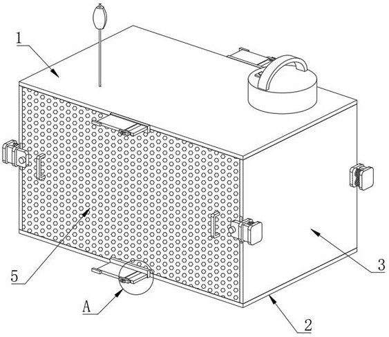
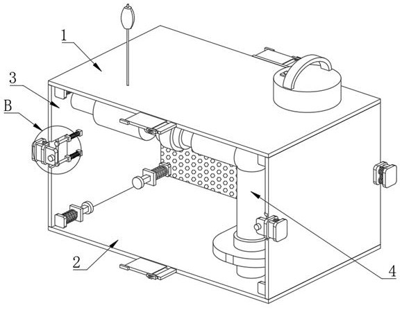
[0034] Example one, by Figure 1 to Figure 9 Given, the present invention comprises a top plate 1, a bottom plate 2 and an aerator body 4, the aerator body 4 is located between the top plate 1 and the bottom plate 2, the top plate 1 and the bottom plate 2 are connected by two side plates 3, and the aerator body 4 Both sides are provided with a filter screen 5, and the adjacent side of the two side plates 3 are provided with two chute 6, one side of the inner wall of the chute 6 is communicated with one side of the side plate 3, the filter screen 5 is Both sides are fixedly connected with a sliding plate 8, and two first baffles 7 are provided on one side of the two filter screens 5 away from each other. There is an elastic pressing component matched with the filter screen 5, and the top plate 1 and the bottom plate 2 are provided with an anti-fall component matched with the filter screen 5;

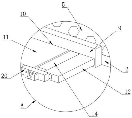
[0035]The anti-fall assembly includes two first fixing plates 9 arranged on the filt...

Embodiment 2

[0036] Embodiment 2, on the basis of Embodiment 1, by figure 1 , image 3 , Figure 5 , Image 6 , Figure 7 and Figure 9 Given, one side of the movable plate 12 is provided with a second groove 17, a limit plate 18 is arranged in the second groove 17, and one side of the limit plate 18 and the inner wall of one side of the second groove 17 pass through two second grooves 17. Two compression springs 19 are connected, a second fixing plate 20 is fixedly connected to one side of the supporting plate 11, a limiting hole 21 is defined on one side of the second fixing plate 20, and a supporting frame 22 is fixedly connected to the second fixing plate 20. The supporting frame 22 is a U-shaped structure, one side of the support frame 22 is provided with a connecting rod 23, the connecting rod 23 penetrates the support frame 22, and one end of the connecting rod 23 is located in the limit hole 21, and both ends of the connecting rod 23 are fixedly connected to the limit plate 24...

Embodiment 3

[0038] Embodiment 3, on the basis of Embodiment 1, by figure 1 , figure 2 , Figure 4 and Figure 8 Given, the elastic pressing assembly includes a push plate 25 and a third fixing plate 26, the third fixing plate 26 is fixedly connected with the side plate 3, a prism 27 is fixedly connected to one side of the pushing plate 25, and the prism 27 penetrates the third fixing plate 26, A third compression spring 28 is sleeved on the outside of the prism 27, two ends of the third compression spring 28 are fixedly connected with the push plate 25 and the third fixing plate 26 respectively, and one end of the prism 27 away from the push plate 25 is fixedly connected with a first anti-fall. The plate 29, one side of the push plate 25 is in contact with one side of the filter screen 5, the reset unit includes a fourth fixing plate 30 arranged on one side of the first baffle 7, and the fourth fixing plate 30 is fixedly connected with the side plate 3, The first baffle plate 7 penetr...


PUM


Abstract

The invention relates to the technical field of aerators, and discloses an aerator with a filter screen, which solves the problems that the aerator is blocked, the later cleaning is inconvenient, the working efficiency is influenced and the actual use is inconvenient due to the rough surface on which sediments and water scales are easy to form on the aerator, and comprises a top plate, a bottom plate and an aerator body, the aerator body is located between the top plate and the bottom plate, the top plate and the bottom plate are connected through two side plates, filter screens are arranged on the two sides of the aerator body, two sliding grooves are formed in the sides, close to each other, of the two side plates, the inner walls of one sides of the sliding grooves are communicated with one sides of the side plates, and sliding plates are fixedly connected to the two sides of the filter screens. The sides, away from each other, of the two filter screens are each provided with two first baffles, and the first baffles and the side plates are connected through reset units. The filter screen can filter impurities, so that the possibility that the impurities are adsorbed to the aerator body is reduced, the frequency of cleaning the aerator body is reduced, and the filter screen is convenient to replace and clean.

Description

technical field [0001] The invention belongs to the technical field of aerators, in particular to an aerator with a filter screen. Background technique [0002] The water flow generated by the aerator passes through the nozzle to form a high-speed water flow. In the mixing chamber, the air is sucked in due to the negative pressure formed around the nozzle. The air meets the high-speed water flow through the throat and is torn into micro-bubbles and water to form a gas-water mixture. , ejected at high speed. The water flow with a large number of air bubbles is in a wide range, generating a strong one-way liquid flow, which combines aeration, agitation and push flow. [0003] The rough surface of the aerator is easy to form deposits and scales, which will lead to the blockage of the aerator, and it is inconvenient to clean up later, which affects the work efficiency and is inconvenient for practical use. SUMMARY OF THE INVENTION [0004] In view of the above situation, in ...

Claims


Application Information

Patent Timeline
IPC IPC(8): C02F7/00B01D29/03B01D29/54B01D29/96
CPCC02F7/00B01D29/03B01D29/54B01D29/96Y02W10/10
Inventor 刘会平凌建军刘霞曹泽明倪阳
Owner LINGZHI ENVIRONMENTAL PROTECTION CO LTD
Why Eureka
Try Eureka