Drawer sliding rail assembly

A technology for drawers and components, which is applied in drawers, furniture parts, household appliances, etc., can solve the problems of large volume of structural adjustment devices, and achieve the effects of compact structure, improved convenience of use, and reduced occupied space

Pending Publication Date: 2022-07-29
GUANGDONG DTC HARDWARE PRECISION MFG CO LTD
View PDF1 Cites 4 Cited by
  • Summary
  • Abstract
  • Description
  • Claims
  • Application Information

AI Technical Summary

Problems solved by technology

The structural adjustment device is bulky, and the adjustment device is installed on the gap between the furniture drawer and the furniture cabinet, so before the drawer and the furniture cabinet are assembled, the adjustment device needs to be installed inside the furniture cabinet

Method used


Image

  • Drawer sliding rail assembly
  • Drawer sliding rail assembly
  • Drawer sliding rail assembly

Examples


no. 1 example

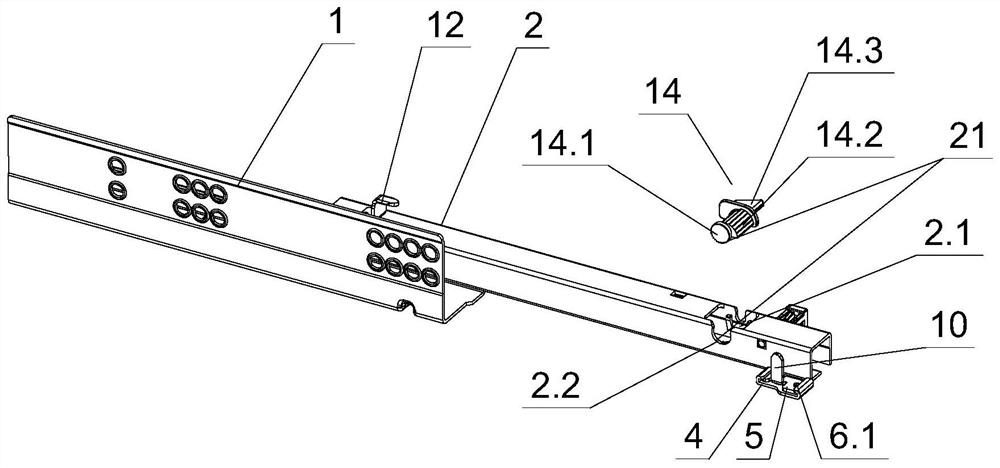
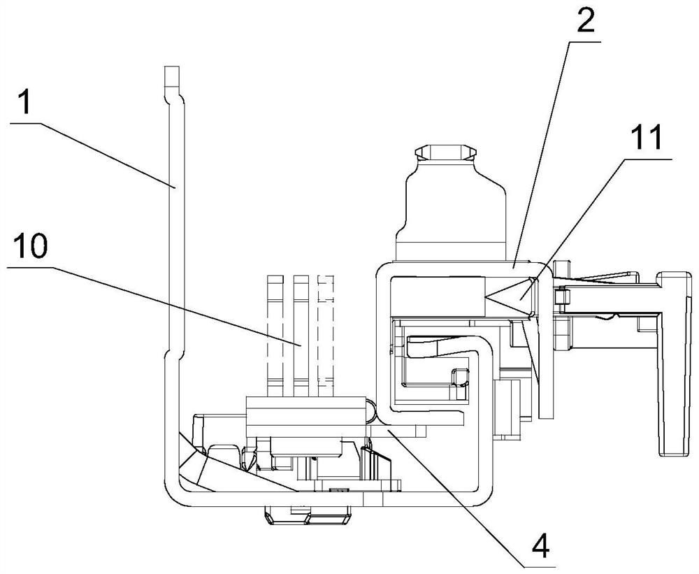
[0057] see Figure 1-Figure 18 , a drawer slide rail assembly, including a fixed slide rail 1 and a movable slide rail 2, a left and right adjustment mechanism is arranged between the fixed slide rail 1 and the movable slide rail 2, and the left and right adjustment mechanism includes a positioning block 4, a movable block 5, and a positioning block. 4 is provided with an adjustment piece, the positioning block 4 and the movable block 5 are respectively matched and connected with the adjustment piece, and the movable block 5 slides left and right on the positioning block 4 through the adjustment piece.

[0058] see Figure 4 , Figure 5 , between the positioning block 4 and the movable block 5 is provided with a guide portion 3 and / or a limit portion 18, and the movable block 5 is positioned and slid on the positioning block 4 through the guide portion 4.2 and / or the limit portion 4.1.

[0059] In this embodiment, the limiting portion 18 includes a limiting groove 4.1 provid...

no. 2 example

[0088] see Figure 24-Figure 33 , A drawer slide rail assembly is different from the first embodiment in that: the movable block 5 is provided with a side post that is inserted into the first insertion hole 8.4, the movable piece 16 is provided on the side post of the movable block 5, and the movable piece 16 The movable member 16 adjusts the inclination 15 (up and down distance) between the bottom plate 8.2 and the movable slide rail 2 during the lifting process.

[0089] In this embodiment, the movable member 16 moves up and down on the side post through screw connection. When the drawer 8 is in a load-bearing state, the front side of the drawer 8 will tilt downward on the movable sliding rail, so a movable piece 16 is provided to adjust the inclination 15 between the bottom plate 8.2 of the drawer 8 and the movable sliding rail 2, and the movable piece 16 is rising. During the process, the extension part 8.3 is moved upward, the bottom plate 8.2 of the drawer 8 can be rais...

no. 3 example

[0092] see Figure 35-Figure 36 , A drawer slide rail assembly is different from the first embodiment in that: the adjusting member is an eccentric rotating disk 7, and the eccentric rotating disk 7 includes a disk body 7.2.

[0093]In this embodiment, the first positioning portion 19 includes a second mounting groove 4.4 provided on the positioning block 4, and an adjusting portion 7.3 located on the bottom of the disk body 7.2. The second installation slot 4.4 is in clearance fit with the adjustment part 7.3, and the adjustment part 7.3 is provided with a cross slot or a slot for inserting a screwdriver. Or by manually twisting the adjustment part 7.3.

[0094] In this embodiment, the second positioning portion 20 includes a spiral groove 7.1 provided on the disk body 7.2, and a plurality of protrusions 5.3 provided on the movable block 5 at intervals. The outer part of the helical groove 7.1 is limited between two adjacent protrusions 5.3 after the eccentric rotating disk...


PUM


Abstract

A drawer sliding rail assembly comprises a fixed sliding rail and a movable sliding rail, a left-right adjusting mechanism is arranged between the fixed sliding rail and the movable sliding rail, the left-right adjusting mechanism comprises a positioning block and a movable block, the movable block is arranged on the positioning block in a sliding mode, an adjusting piece is arranged on the positioning block, and the positioning block and the movable block are connected with the adjusting piece in a matched mode. The movable block slides left and right on the positioning block through the adjusting piece. The left-right adjusting mechanism is independently arranged on the movable sliding rail, and compared with an existing left-right adjusting mechanism between the drawer and the cabinet body, the left-right adjusting mechanism is simpler, lower in cost and easy to assemble. The left-right adjusting mechanism is independently arranged on the movable sliding rail, and compared with an existing left-right adjusting mechanism between the drawer and the cabinet body, the left-right adjusting mechanism is simpler, lower in cost and easy to assemble. On the premise of not changing the assembly (appearance) between the drawer and the sliding rail assembly, the left-right adjusting function of adjusting the left-right gap between the drawer and the cabinet body can be achieved, the product is more attractive and simpler, and the assembly effect is improved.

Description

technical field [0001] The invention relates to a drawer, in particular to a drawer slide rail assembly. Background technique [0002] Chinese Patent Document No. CN107568963A discloses an adjustable furniture drawer structure on 2018.01.12, including furniture drawer, furniture cabinet and slide rail assembly, the furniture drawer is movably opened and closed on the furniture drawer through the slide rail assembly, the furniture drawer and furniture A gap portion is arranged between the cabinet bodies, and an adjustment device is arranged on the gap portion, and the adjustment device is respectively matched and connected with the furniture drawer and the furniture cabinet body. , and / or up and down relative position adjustment. The structural adjustment device is bulky, and the adjustment device is arranged on the gap between the furniture drawer and the furniture cabinet, so before the drawer and the furniture cabinet are assembled, the adjustment device needs to be insta...

Claims


Application Information

Patent Timeline
Patent Type & Authority Applications(China)
IPC IPC(8): A47B88/407A47B88/90
CPCA47B88/407A47B88/90
Inventor 伍志勇
Owner GUANGDONG DTC HARDWARE PRECISION MFG CO LTD
Why Eureka
Try Eureka