
Cover welding machine

A technology of welding capping machine and welding machine, which is applied to conveyors, welding equipment, non-electric welding equipment, etc., can solve the problems of welding tool and welding machine offset, poor welding quality, damage to transfer mechanism or other mechanisms, etc.

Pending Publication Date: 2022-07-29
广州达辰设备制造有限公司
View PDF0 Cites 0 Cited by
  • Summary
  • Abstract
  • Description
  • Claims
  • Application Information

AI Technical Summary

Problems solved by technology

At present, the welding device used for bottle caps generally includes a base and a turntable that is rotatably arranged on the base. Several welding frocks are arranged on the turntable, and the welding frocks are fixedly connected on the turntable. In order to ensure that the turntable does not interfere with the base when it is rotating, a certain gap needs to be left between the turntable and the base; a welding machine is installed outside the turntable, and the welding machine will press down the inner cover of the welding tool and weld it during welding , after a long time of welding work, the turntable will be deformed downward, which will cause the welding tool and welding machine to deviate, resulting in poor welding quality or even no welding
[0003] And when the transfer mechanism transfers the outer cover and the inner cover, the outer cover or the inner cover generally moves obliquely. During the movement, the outer cover, the inner cover or the transfer mechanism are likely to collide with other mechanisms, resulting in Cover falls off or damages transfer mechanism or other mechanism

Method used


Image

  • Cover welding machine
  • Cover welding machine
  • Cover welding machine

Examples


Embodiment Construction

[0041]The present invention will be further described below with reference to the accompanying drawings and specific embodiments. It should be noted that, on the premise of no conflict, the embodiments or technical features described below can be combined arbitrarily to form new embodiments. .

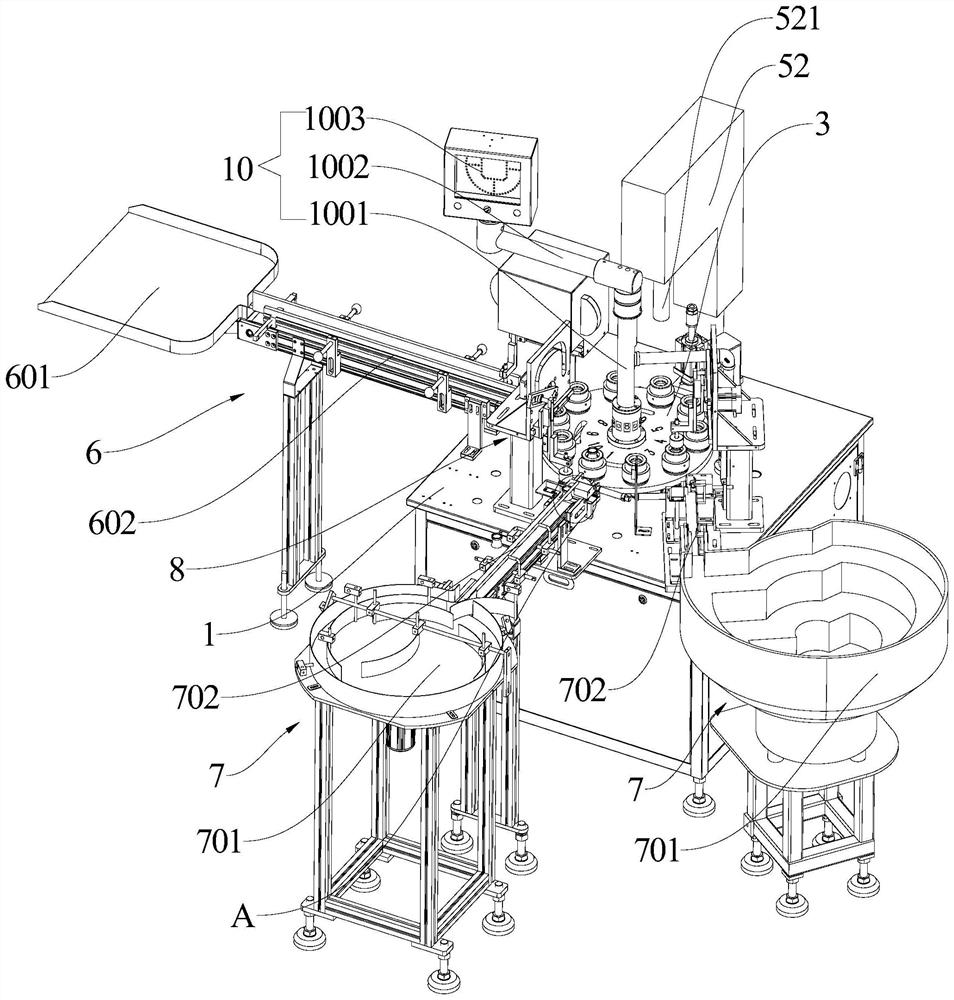
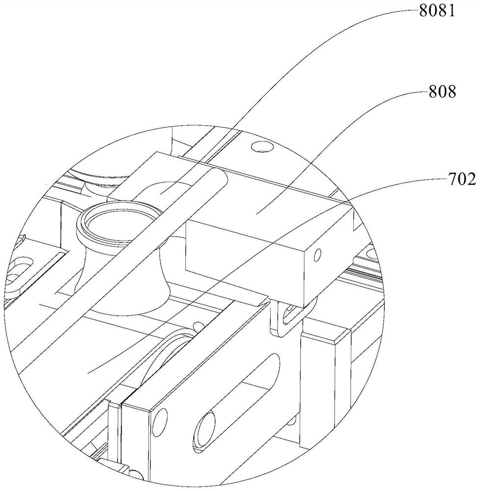
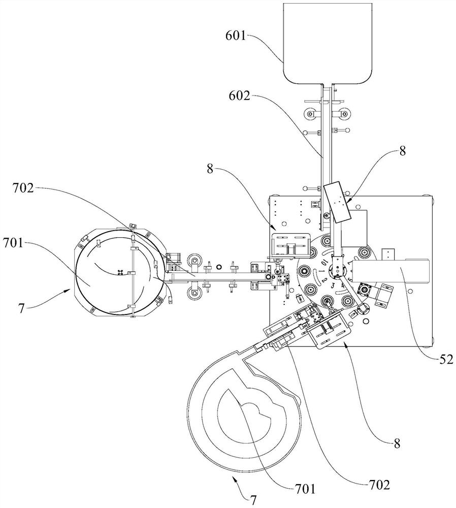
[0042] like Figure 1-15 As shown, the present application invents a cap welding machine, comprising a base 1, a driving mechanism 2, a turntable 3, a welding tool 4, a welding mechanism 5, a discharging mechanism 6, at least one feeding mechanism 7 and at least two transferring mechanisms 8;

[0043] The turntable 3 is rotatably mounted on the base 1, the drive mechanism 2 is used to drive the turntable 3 to rotate, and the welding tool 4 is mounted on the turntable 3. Specifically, the drive mechanism 2 includes a motor 21 and a reducer 22, and the motor 21 and the reducer 22. All are arranged in the base 1, the motor 21 is connected with the reducer 22, and the reducer 22 is connec...


PUM


Abstract

The invention discloses a cover welding machine which comprises a base, a driving mechanism, a rotating disc, a welding tool, a welding mechanism, a discharging mechanism, at least one feeding mechanism and at least two transferring mechanisms, the rotating disc is rotatably installed on the base, the driving mechanism is used for driving the rotating disc to rotate, the welding tool is installed on the rotating disc, and the welding mechanism is used for welding the welding tool. The welding mechanism comprises a welding machine, the welding machine is arranged on the base, a welding head of the welding machine is located above the rotary disc, the rotary disc can enable the welding tool to move to the position below the welding head of the welding machine, and the cover welding machine can effectively prevent the welding tool from moving to the position below the welding head of the welding machine in the transferring process. The outer cap, the inner cap, or the transfer mechanism collides with other mechanisms.

Description

technical field [0001] The invention relates to the technical field of ultrasonic welding equipment, in particular to a cap welding machine. Background technique [0002] The caps of cosmetic bottles on the market generally include an inner cap and an outer cap, and ultrasonic welding is usually used between the inner cap and the outer cap to fasten the two. At present, the welding device for bottle caps generally includes a base and a turntable rotatably arranged on the base. A number of welding tools are arranged on the turntable, the welding tools are fixedly connected to the turntable, and the welding tools are used to place the outer cap and the inner cap, and In order to ensure that the turntable does not interfere with the base when it rotates, there needs to be a certain gap between the turntable and the base; there is a welding machine outside the turntable, and the welding machine will press down the inner cover of the welding tool and weld it during welding. , Af...

Claims


Application Information

Patent Timeline
Patent Type & Authority Applications(China)
IPC IPC(8): B23K20/10B23K20/26B65G27/04B65G27/16B65G47/14B23K101/12
CPCB23K20/10B23K20/26B65G47/1421B65G27/04B65G27/16B23K2101/12
Inventor 朱瑞贤
Owner 广州达辰设备制造有限公司
Learn More