Automatic assembling device for coupler diaphragm

A technology of automatic assembly device and coupling, applied in assembly machines, metal processing equipment, manufacturing tools, etc., can solve problems such as low work efficiency, affecting assembly accuracy and quality, and pressing position offset, so as to reduce man-hours and improve The effect of work efficiency

Pending Publication Date: 2022-07-29
浙江海能传动机械股份有限公司
View PDF0 Cites 2 Cited by
  • Summary
  • Abstract
  • Description
  • Claims
  • Application Information

AI Technical Summary

Problems solved by technology

[0003] However, the assembly work of the existing coupling diaphragm usually requires manual pre-assembly of the screw ring and the screw on the assembly hole, the work efficiency is low, and the diaphragm needs to be manually rotated to switch the assembly hole, which increases the length of manual operation, and The diaphragm cannot be fixed when pressed, and there will be a problem of offset of the pressed position, which will affect the accuracy and quality of assembly

Method used


Image

  • Automatic assembling device for coupler diaphragm
  • Automatic assembling device for coupler diaphragm
  • Automatic assembling device for coupler diaphragm

Examples


Embodiment 1

[0031] The following describes in detail the embodiments of the present invention, examples of which are illustrated in the accompanying drawings, wherein the same or similar reference numerals refer to the same or similar elements or elements having the same or similar functions throughout. The embodiments described below with reference to the accompanying drawings are exemplary, and are intended to explain the present invention and should not be construed as limiting the present invention.

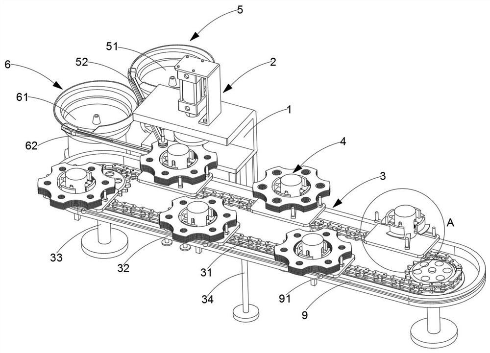
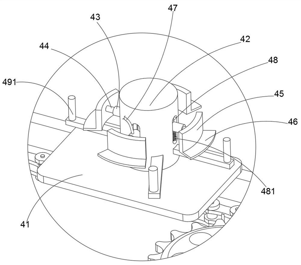
[0032] like Figure 1 to Figure 7 As shown in the figure, a coupling diaphragm automatic assembly device includes a frame 1, a pressing component 2 is arranged on the frame 1, a rotary component 3 is arranged below the frame 1, and a plurality of stable Assembly 4, the rear of the rotary assembly 3 is also provided with a feeding assembly a5 and a feeding assembly b6, a rotating assembly 7 is also provided below the rotary assembly 3, and a linkage assembly 8 is also provided between the...

Embodiment 2

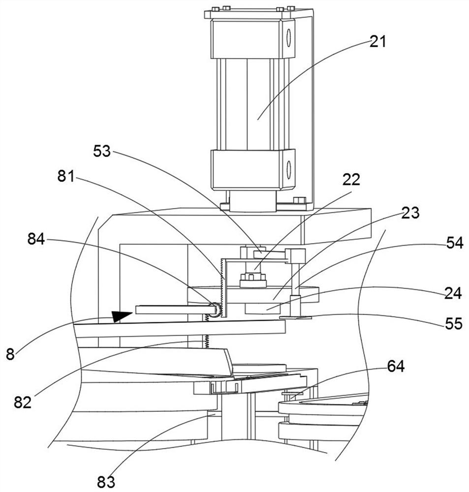
[0043] like Figure 4 As shown in the figure, the same or corresponding parts as in the first embodiment are marked with the corresponding reference numerals as in the first embodiment. For the sake of brevity, only the differences from the first embodiment are described below; the difference between the second embodiment and the first embodiment The point is that both the negative pressure suction cup 55 and the lifting plate 65 are provided with buffer protection pads.

[0044] Here, in this embodiment, buffer protection pads are provided on both the negative pressure suction cup 55 and the lifting plate 65, so that when the negative pressure suction cup 55 moves downward to cooperate with the screw ring 13, it plays a buffering role, and the lifting plate 65 moves upward. When moving together with the screw 14, it acts as a buffer, reduces the possibility of wear of the screw ring 13 and the screw 14, and increases the service life of the negative pressure suction cup 55, t...


PUM


Abstract

The invention relates to an automatic coupler diaphragm assembling device which comprises a rack, a material pressing assembly is arranged on the rack, a rotating assembly is arranged below the rack, a plurality of stabilizing assemblies are arranged on the rotating assembly in an array mode, a material supply assembly a and a material supply assembly b are further arranged behind the rotating assembly, and a rotating assembly is further arranged below the rotating assembly. A linkage assembly is further arranged between the feeding assembly a and the feeding assembly b, and the stabilizing assembly is used for being unfolded after being inflated to fix the membrane and being matched with the rotating assembly in the conveying process along the rotating assembly to be driven by the rotating assembly to switch assembly holes of the membrane. And the material pressing assembly is used for driving the material supply assembly a to move downwards in the downward pressing process to place the screw ring at the top of the assembly hole and driving the material supply assembly b to move upwards under the action of the linkage assembly to sleeve the screw into the assembly hole, so that the assembly efficiency and precision are improved.

Description

technical field [0001] The invention relates to the technical field of couplings, and more particularly relates to an automatic assembling device for coupling diaphragms. Background technique [0002] The coupling diaphragm is formed by stacking several diaphragms, which are assembled together by screw rings and screws. [0003] However, the assembling work of the existing coupling diaphragm usually requires manual pre-assembly of the screw ring and the screw on the assembly hole, which has low work efficiency, and requires manual manual rotation of the diaphragm to switch the assembly hole, which increases the manual operation time, and The diaphragm cannot be fixed during pressing, and there will be a problem of displacement of the pressing position, which affects the accuracy and quality of the assembly. SUMMARY OF THE INVENTION [0004] The purpose of the present invention is to provide an automatic assembling device for the coupling diaphragm in view of the deficienc...

Claims


Application Information

Patent Timeline
Patent Type & Authority Applications(China)
IPC IPC(8): B23P21/00
CPCB23P21/004
Inventor 张华
Owner 浙江海能传动机械股份有限公司
Why Eureka
Try Eureka