
Adjustable vacuum circuit breaker energy storage spring assembling and disassembling tool

A technology of vacuum circuit breaker and energy storage spring, applied in the field of adjustable vacuum circuit breaker energy storage spring loading and unloading tools, can solve the problems of easy deformation of the energy storage spring, difficult control of the energy storage spring, bullet damage to staff and equipment, etc. The effect of preventing popping or falling off, improving reliability, and improving safety

Pending Publication Date: 2022-07-29
国网江苏省电力有限公司宝应县供电分公司 +1
View PDF17 Cites 0 Cited by
  • Summary
  • Abstract
  • Description
  • Claims
  • Application Information

AI Technical Summary

Problems solved by technology

In addition to time-consuming and labor-intensive disassembly, this disassembly also has the following problems: (1) the energy storage spring is difficult to control during disassembly and assembly, and can damage staff and equipment; (2) the energy storage spring is often deformed by destructive forces, Decreased storage capacity affects the closing power; (3) The disassembly and assembly technology is difficult and requires high coordination accuracy; (4) The disassembly and assembly work is intensive and requires high physical strength

Method used


Image

  • Adjustable vacuum circuit breaker energy storage spring assembling and disassembling tool
  • Adjustable vacuum circuit breaker energy storage spring assembling and disassembling tool
  • Adjustable vacuum circuit breaker energy storage spring assembling and disassembling tool

Examples


Embodiment Construction

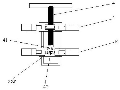
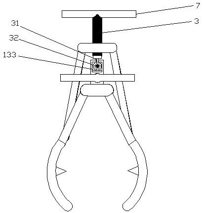
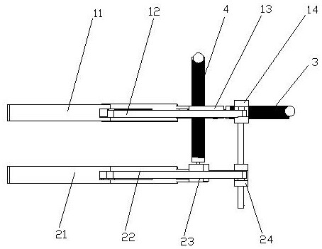
[0047] The present invention is as Figure 1-9 As shown, it includes an upper clamping arm assembly 1, a lower clamping arm assembly 2, a clamping screw 3 and a lifting screw 4,

[0048] The upper clamping arm assembly 1 includes a pair of upper clamping arms 11 , a pair of upper connecting rods 12 , an upper connecting plate 13 and an upper fixed clamping plate 14 , a pair of upper clamping arms 11 are symmetrically arranged, and the upper connecting rods 12 and the upper clamp The arms 11 are in one-to-one correspondence and are located on the outer side of the upper clamping arm,

[0049] One end of a pair of upper connecting rods 12 is symmetrically connected to both ends of the upper fixed clamping plate 14, and the other end is hingedly connected to the middle of the upper clamping arm 11.

[0050] The upper connecting plate 13 is located between a pair of upper connecting rods. The upper connecting plate 13 is T-shaped and has a horizontal section 131 and a vertical se...


PUM


Abstract

The invention discloses an adjustable vacuum circuit breaker energy storage spring assembling and disassembling tool. Relates to a circuit breaker auxiliary device. Comprising an upper clamping arm assembly, a lower clamping arm assembly, a clamping screw rod and a lifting screw rod, the upper clamping arm assembly comprises a pair of upper clamping arms, a pair of upper connecting rods, an upper connecting plate and an upper fixing clamping plate, the upper clamping arms are symmetrically arranged, and the upper connecting rods correspond to the upper clamping arms one to one and are located on the outer sides of the upper clamping arms; one ends of the pair of upper connecting rods are symmetrically hinged to the two ends of the upper fixing clamping plate, the other ends of the upper connecting rods are hinged to the middle of the upper clamping arm, and the upper connecting plate is located between the pair of upper connecting rods, is in a T shape and is provided with a horizontal section and a vertical section. The two ends of the horizontal section of the upper connecting plate are hinged to the ends, facing the upper connecting plate, of the pair of upper clamping arms respectively, and the clamping screw is movably connected to the upper fixing clamping plate and used for pushing and pulling the upper connecting plate. The operation can be completed by a single person, and the spring can be prevented from jumping out or falling off in the midway; meanwhile, the shaft pin is prevented from being stressed, and reliability is improved.

Description

technical field [0001] The invention relates to a circuit breaker auxiliary appliance, in particular to an adjustable vacuum circuit breaker energy storage spring loading and unloading tool. Background technique [0002] VS1 type vacuum circuit breaker has a compact design, the closing spring is in front of the closing coil, and the energy storage spring must be removed when there is adjustment and maintenance of the closing iron core or ejector rod, and the work of replacing the closing coil. When removing the stored energy spring, it needs to be stretched before the spring retaining pin can be pulled out. Due to the large elastic force of the energy storage spring (700N), a large shear force is generated on the spring fixed shaft pin, which makes it difficult to disassemble and assemble the spring fixed shaft pin. [0003] The main method of traditional disassembly is that two people work together, one person uses a steel screwdriver to pry open the energy storage spring ...

Claims


Application Information

Patent Timeline
Patent Type & Authority Applications(China)
IPC IPC(8): B25B27/30
CPCB25B27/30
Inventor 赵海清朱淼蔡一凡蒋俊倪国勇孙向宇孙宁海仲怀军陈诚付蕾
Owner 国网江苏省电力有限公司宝应县供电分公司
Learn More