Weight gravity center measuring device

A technology of measuring device and center of gravity position, which is used in measuring device, weighing, testing of machine/structural components, etc. Measuring the effect of interference

Pending Publication Date: 2022-07-29
CHENGDU AIRCRAFT INDUSTRY GROUP
View PDF8 Cites 0 Cited by
  • Summary
  • Abstract
  • Description
  • Claims
  • Application Information

AI Technical Summary

Problems solved by technology

[0004] Among them, especially when the weight center of gravity is measured by jacking, the essence is to use the principle of moment balance and the balance equation of the static force system to calculate the coordinates of the center of gravity of the drone. In the process, it is necessary to lift a specific point of the drone to change its attitude. For example, when the wing on one side of the UAV is lifted, the wing will be deformed due to the force, which will drive the top of the measuring device fixedly connected to the wing to displace in the horizontal direction, causing the measuring device to tilt in the vertical direction, making the scale The heavy sensor is affected by the lateral force, resulting in a decrease in measurement accuracy; in severe cases, the measurement device will be separated from the drone, causing the drone to scratch

Method used


Image

  • Weight gravity center measuring device
  • Weight gravity center measuring device
  • Weight gravity center measuring device

Examples


Embodiment 1

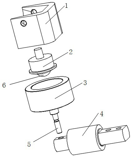
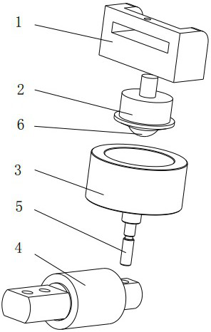
[0033] A device for measuring the center of gravity of this embodiment, such as figure 1 and figure 2 As shown, it is a measuring device for measuring the weight and the position of the center of gravity of the UAV; it includes a connecting piece 1, a roller mechanism, a supporting piece, a load cell 4 and a jacking mechanism arranged in sequence from top to bottom;

[0034] Connector 1, the connector 1 is used to connect the drone; such as figure 1 The shown connector 1 is used to connect the fuselage of the UAV, so it has a concave structure in a U-shape or a C-shape to adapt to the bottom profile of the fuselage of the UAV or to be installed through the concave structure to be more suitable for unmanned aerial vehicles. The bracket of the outline of the fuselage; at the same time, figure 1 There are also hanging holes on the two side plates of the connecting piece 1 in the above, and the hanging holes can be used to install the locking belt to realize the fixing of the f...

Embodiment 2

[0041] This embodiment is further optimized on the basis of Embodiment 1. As shown in the figure, when the roller part 6 and the fixing part 2 are connected by a spherical pair, the roller part 6 is a sphere, and the roller part 6 is locked. It is embedded in the ball socket of the fixing part 2 .

[0042] When the roller part 6 is connected with the fixed part 2 through a rolling pair, the roller part 6 is a sphere, and the fixed part 2 has a casing for accommodating the roller part 6 in a snap fit. The inner wall of the casing is provided with steel balls, and the inner wall of the casing is connected with the sphere through the steel balls; the roller mechanism here can be a bull's eye bearing.

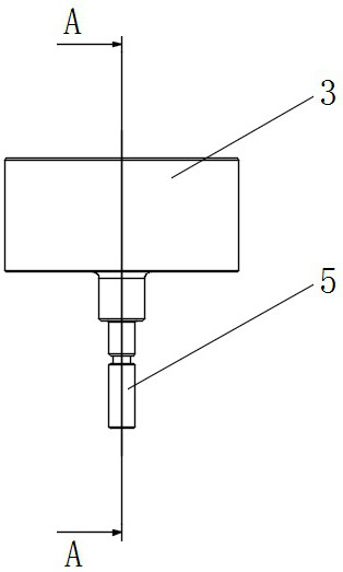
[0043] The support part 3 includes a circular support tray 7 arranged horizontally, the top of the support tray 7 is a micro-arc surface concave toward the center, and the sphere and the micro-arc surface are connected by a rolling pair, The top edge of the support tray 7 extends ...

Embodiment 3

[0049] This embodiment is further optimized on the basis of Embodiment 1. When the roller part 6 and the fixed part 2 are connected by a rotating pair, the roller part 6 is a revolving body, and the revolving body rotates along its own A rotating shaft is provided in the direction of the center line, and the rotating body is rotatably connected to the fixed part 2 through the rotating shaft.

[0050] The other parts of this embodiment are the same as the above-mentioned Embodiment 1, and thus are not repeated here.


PUM


Abstract

The invention relates to the technical field of measuring the weight center of gravity of an unmanned aerial vehicle, and discloses a weight center of gravity measuring device which comprises a connecting piece used for being connected with the unmanned aerial vehicle; the roller mechanism is provided with a fixing part and a roller part, the fixing part is used for being connected with the connecting piece, and the fixing part and the roller part are connected through a rotating pair or a spherical pair or a rolling pair; the bearing piece is provided with a bearing part and a supporting part, and the bearing part is used for bearing the roller mechanism and is connected with a roller part of the roller mechanism through a rolling pair; the bottom of the bearing part is fixedly connected with the supporting part; the weighing sensor is used for being connected with the supporting part and measuring the unremembered weight; and the jacking mechanism is used for fixing the weighing sensor and adjusting the height of the weighing sensor. The interference of the lateral force generated by the stress shape edge of the unmanned aerial vehicle on the measurement accuracy of the weight center of gravity is avoided.

Description

technical field [0001] The invention relates to the technical field of measuring the weight center of an unmanned aerial vehicle, in particular to a weight center of gravity measuring device, which is used to determine the center of gravity of the unmanned aerial vehicle and weigh the weight of the unmanned aerial vehicle. Background technique [0002] UAVs have been widely and deeply used in various fields such as military reconnaissance, environmental monitoring, meteorological monitoring, environmental law enforcement, geographic survey, land survey law enforcement, and forest fire prevention. During the take-off, landing and flight of the UAV, the weight and center of gravity of the UAV will affect the lift and flight of the UAV, and the UAV is easily affected by airflow disturbance during the flight, which makes the UAV If the flight attitude of the drone is changed or caused, to restore the normal flight attitude of the drone, the power adjustment should be performed a...

Claims


Application Information

Patent Timeline
Patent Type & Authority Applications(China)
IPC IPC(8): G01M1/12G01G19/07
CPCG01M1/125G01G19/07
Inventor 花为民张锋唐茂华
Owner CHENGDU AIRCRAFT INDUSTRY GROUP
Why Eureka
Try Eureka