Electric energy metering device
An energy metering device and voltage technology, which is applied in the direction of measuring device, measuring electrical variable, measuring time integration, etc., can solve the problems of interference current, voltage signal measurement, inconvenient maintenance work, complicated wiring method, etc. The effect of facilitating wiring and compressing the current wiring space
- Summary
- Abstract
- Description
- Claims
- Application Information
AI Technical Summary
Problems solved by technology
Method used
Image
Examples
Embodiment 1
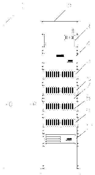
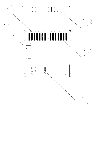
[0024] An electrical energy metering device such as figure 1 , figure 2 The shown cabinet 2 is provided with a processor 4 and a control unit 3 connected to the processor, and a voltage transformer 13 is provided above the control unit 3 on the cabinet, and the voltage input terminal of the control unit is connected to the voltage provided on the cabinet. Terminal 15, the voltage terminal 15 is connected to the secondary winding of the voltage transformer 13, and the primary winding of the voltage transformer 13 is connected to the voltage incoming terminal 11 provided on the cabinet.
Embodiment 2
[0026] An electrical energy metering device such as figure 1 , figure 2 As shown, it includes a cabinet 2 and a cabinet door 1, the cabinet 2 is provided with a processor 4 and a control unit 3 connected to the processor 4, the control unit 3 is also connected with an attached table, and the control unit 3 is provided with A voltage input terminal 12 and a voltage output terminal 14, the voltage input terminal 12 is connected to the voltage terminal 15 of the processor 4, the voltage output terminal 14 is connected to the voltage transformer 13 above the control unit 3, and the voltage transformer 13 is connected to the voltage incoming terminal 11, and the voltage incoming terminal 11 includes eight voltage loops;
[0027] The control unit 3 is connected to the schedule through a current transformer, and the schedule includes four schedules, and each schedule includes six current loops; the processor 4 is connected to the first schedule 5, and the first schedule Schedule ...
Embodiment 3
[0029] An electrical energy metering device such as figure 1 , figure 2 As shown, it includes a cabinet 2 and a cabinet door 1, the cabinet 2 is provided with a processor 4 and a control unit 3 connected to the processor 4, the control unit 3 is also connected with an attached table, and the control unit 3 is provided with A voltage input terminal 12 and a voltage output terminal 14, the voltage input terminal 12 is connected to the voltage terminal 15 of the processor 4, the voltage output terminal 14 is connected to the voltage transformer 13 above the control unit 3, and the voltage transformer 13 is connected to the voltage incoming terminal 11, and the voltage incoming terminal 11 includes eight voltage loops;
[0030] The control unit 3 is connected to the schedule through a current transformer, and the schedule includes four schedules, and each schedule includes six current loops; the processor 4 is connected to the first schedule 5, and the first schedule Schedule ...
PUM
 Abstract
Description
Claims
Application Information
 - R&D
- Intellectual Property
- Life Sciences
- Materials
- Tech Scout
- Unparalleled Data Quality
- Higher Quality Content
- 60% Fewer Hallucinations
Browse by: Latest US Patents, China's latest patents, Technical Efficacy Thesaurus, Application Domain, Technology Topic, Popular Technical Reports.
© 2025 PatSnap. All rights reserved.Legal|Privacy policy|Modern Slavery Act Transparency Statement|Sitemap|About US| Contact US: help@patsnap.com


