Wafer detection device and method

A technology of detection device and detection method, which is applied in distance measurement, line-of-sight measurement, surveying and navigation, etc., can solve problems affecting the accuracy of measurement, and achieve the effect of simple installation and small quantity

Pending Publication Date: 2022-07-29
北京晶亦精微科技股份有限公司
View PDF0 Cites 0 Cited by
  • Summary
  • Abstract
  • Description
  • Claims
  • Application Information

AI Technical Summary

Problems solved by technology

[0004] However, the wafer-parallel unit of the above device requires at least two components, and the two components are respectively installed at relative

Method used


Image

  • Wafer detection device and method
  • Wafer detection device and method
  • Wafer detection device and method

Examples


Embodiment Construction

[0035] The technical solutions of the present invention will be clearly and completely described below with reference to the accompanying drawings. Obviously, the described embodiments are a part of the embodiments of the present invention, but not all of the embodiments. Based on the embodiments of the present invention, all other embodiments obtained by those of ordinary skill in the art without creative efforts shall fall within the protection scope of the present invention.

[0036]In the description of the present invention, it should be noted that the terms "center", "upper", "lower", "left", "right", "vertical", "horizontal", "inner", "outer", etc. The indicated orientation or positional relationship is based on the orientation or positional relationship shown in the accompanying drawings, which is only for the convenience of describing the present invention and simplifying the description, rather than indicating or implying that the indicated device or element must have...


PUM


Abstract

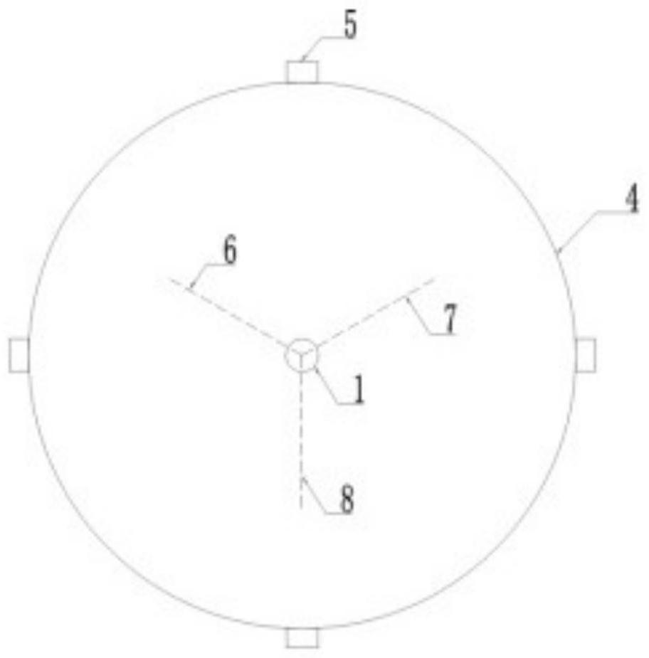
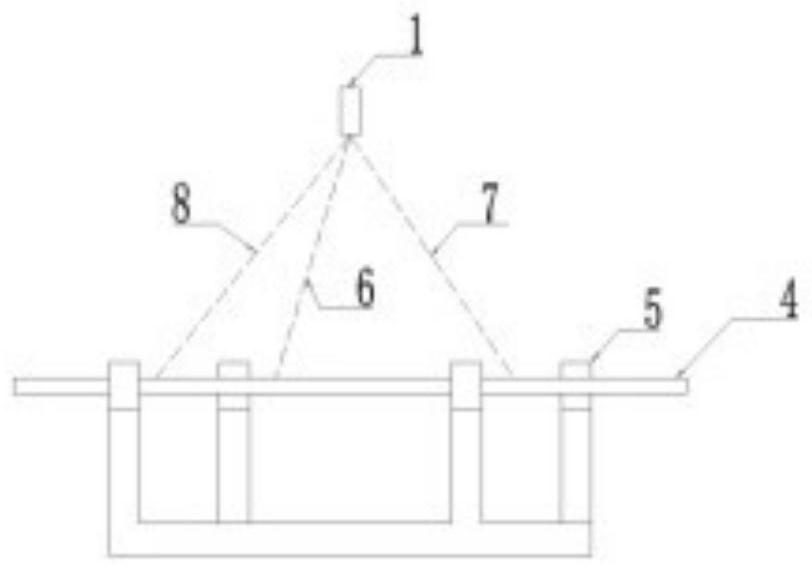
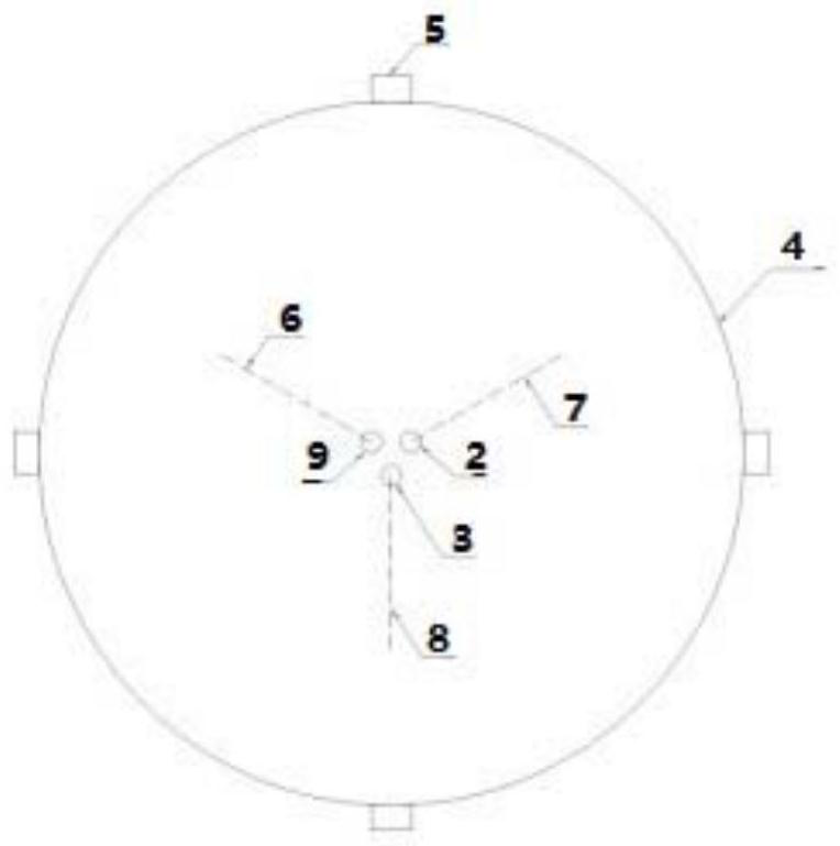
The invention relates to the technical field of semiconductor detection, in particular to a wafer detection device and method and device, and the device comprises at least one light beam generator and a signal processing unit. The light beam generator is mounted on one side of the surface of the wafer; the method comprises the steps that at least three ranging light beams are emitted to the surface of a wafer, reflected light signals are converted into electric signals, and intersection points of the three ranging light beams and the surface of the wafer are not collinear; the signal processing unit receives the electric signal, converts the electric signal into a distance value, compares the distance value with a corresponding set interval, and determines that the wafer is in a horizontal position when the distance value is in the corresponding set interval; when at least one distance value exceeds the corresponding set interval, judging that the wafer is inclined; according to the technical scheme, whether the wafer is horizontal or not is detected, the light beam sensor is installed in a concentrated mode, leveling and alignment are not needed, and the situation that due to the inaccurate installation position of the light beam generator, the detection accuracy is poor is avoided.

Description

technical field [0001] The present invention relates to the technical field of semiconductor inspection, in particular to a wafer inspection device and method. Background technique [0002] Semiconductor components are electronic circuits formed by lithography, etching, various chemical deposition and planarization processes on wafers (silicon wafers). In order to form the required pattern on the wafer, in the semiconductor process, the pattern is first defined by means of lithography, and then the pattern is formed by removing the redundant part by means of etching. After the wafer is etched, a chemical mechanical planarization (Chemical Mechanical Planarization, CMP) process is required. CMP equipment typically includes a semiconductor equipment front end module (EFEM), a cleaning unit, and a polishing unit. The cleaning and drying device of the existing CMP cleaning unit, such as a device for cleaning and drying wafers by spin drying (Spin Rinse Dry, SRD), or a device f...

Claims


Application Information

Patent Timeline
IPC IPC(8): G01S17/48
CPCG01S17/48
Inventor 廉金武张为强王嘉琪赵磊郭益言梅辰萌
Owner 北京晶亦精微科技股份有限公司
Why Eureka
Try Eureka