Computer professional video card heat dissipation system and heat dissipation method

A heat dissipation system and computer technology, applied in the direction of calculation, instrumentation, digital processing power distribution, etc., can solve the problems of messy wiring, gold finger wear, unfavorable fan blade cleaning, etc., and achieve the effect of easy installation and simple operation

Inactive Publication Date: 2022-07-29
山东水利职业学院
View PDF0 Cites 0 Cited by
  • Summary
  • Abstract
  • Description
  • Claims
  • Application Information

AI Technical Summary

Problems solved by technology

[0003] However, the current fans for graphics card heat dissipation are firstly connected to the heat sink and the graphics card when installing, and then the heat sink is connected to the housing, and the fan is installed on the housing by screws. When the fan needs to be cleaned Need to disassemble the screws one by one to clean the dust of multiple fans, it is difficult to quickly disassemble multiple fan blades, which is not conducive to cleaning the fan blades; and when the graphics card is connected to the host, there will be cables between the graphics card and the fans , the graphics card is not equipped with a mechanism to fix the cables, causing the cables to be messy, which is not conducive to the connection and installation of other cables, and affects the later maintenance; and the gold finger part of the graphics card is not equipped with a protective mechanism during maintenance, which is likely to cause golden Worn fingers, resulting in poor contact

Method used


Image

  • Computer professional video card heat dissipation system and heat dissipation method
  • Computer professional video card heat dissipation system and heat dissipation method
  • Computer professional video card heat dissipation system and heat dissipation method

Examples


Embodiment Construction

[0034] In order to make it easy to understand the technical means, creative features, achieved goals and effects of the present invention, the present invention will be further described below with reference to the specific embodiments.

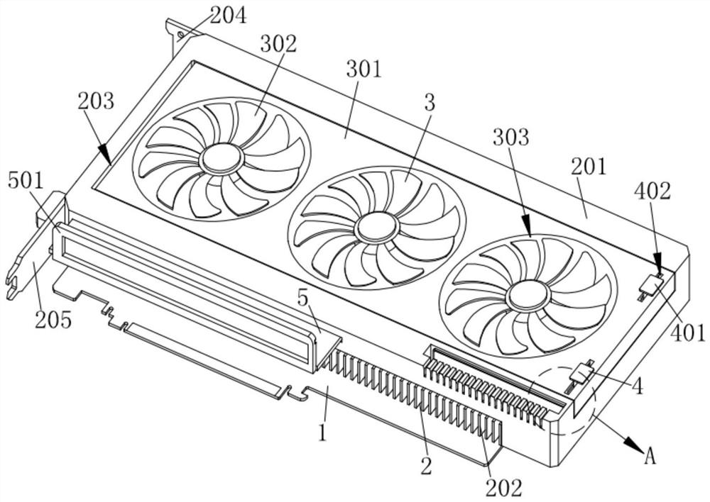
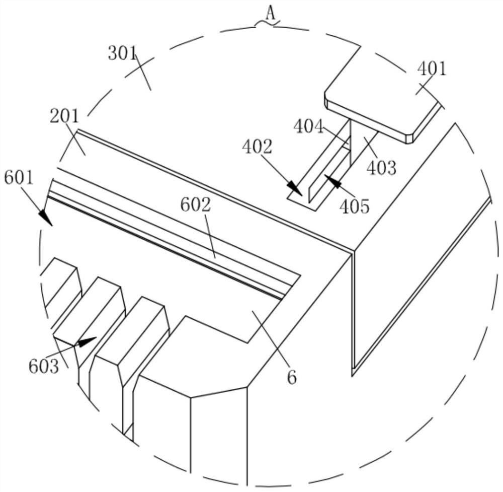
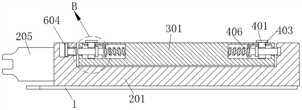
[0035] like Figure 1-Figure 9 As shown in the figure, a computer professional graphics card cooling system according to the present invention includes a graphics card motherboard 1; a heat conduction mechanism 2 is fixedly connected to the graphics card motherboard 1, and a heat dissipation mechanism 3 is arranged on the heat conduction mechanism 2. Two installation mechanisms 4 are installed on the mechanism 3 opposite to each other. The two installation mechanisms 4 extend to the heat conduction mechanism 2. The heat conduction mechanism 2 is installed with a wire clamping mechanism 6 for clamping the cable. The mechanism 6 is in conflict with one of the installation mechanisms 4, and the heat conduction mechanism 2 is provided with a prot...


PUM


Abstract

The invention relates to the technical field of graphics card heat dissipation, in particular to a computer professional graphics card heat dissipation system and heat dissipation method. A heat conduction mechanism is fixedly connected to the display card mainboard, a heat dissipation mechanism is arranged on the heat conduction mechanism, two installation mechanisms are oppositely installed on the heat dissipation mechanism and extend to the heat conduction mechanism, and a wire clamping mechanism for clamping a flat cable is installed on the heat conduction mechanism. The wire clamping mechanism abuts against one of the mounting mechanisms, and a protection mechanism for protecting the golden finger part of the display card mainboard is mounted on the heat conduction mechanism; the heat conduction mechanism is provided with the two mounting mechanisms, when the heat dissipation mechanism needs to be disassembled for dust removal, the two mounting mechanisms slide relatively, the two mounting mechanisms are separated from the heat conduction mechanism, at the moment, a flat cable of the heat dissipation mechanism is separated from a display card mainboard, the heat dissipation mechanism can be pulled out from the heat conduction mechanism, and cleaning of the heat dissipation mechanism is achieved; the operation is simple.

Description

technical field [0001] The invention relates to the technical field of heat dissipation of graphics cards, in particular to a heat dissipation system and a heat dissipation method of graphics cards for professional use in computers. Background technique [0002] The graphics card is to convert the display information required by the computer system to drive the display, and to provide progressive or interlaced scanning signals to the display to control the correct display of the display. The form of the fan with the heat sink is also called active cooling and passive cooling. Active cooling is to install a fan on the graphics card to dissipate it. [0003] However, when installing the current fan for cooling the graphics card, firstly connect the heat sink to the graphics card, and then connect the heat sink to the casing, and install the fan on the casing with screws. When the fan needs to be cleaned It is necessary to remove the screws one by one to clean multiple fans. I...

Claims


Application Information

Patent Timeline
Patent Type & Authority Applications(China)
IPC IPC(8): G06F1/20G06F1/18
CPCG06F1/206G06F1/183
Inventor 黄萌刘春燕钱玉霞
Owner 山东水利职业学院
Why Eureka
Try Eureka