
Robot telescopic swing mechanism and bionic robot

A bionic robot, stretching and swinging technology, applied in the field of bionic robots, can solve the problem of small application range, achieve the effect of wide application range and extended grasping distance

Pending Publication Date: 2022-08-05
ZHENGZHOU UNIV
View PDF7 Cites 0 Cited by
  • Summary
  • Abstract
  • Description
  • Claims
  • Application Information

AI Technical Summary

Problems solved by technology

[0007] The purpose of the present invention is to provide a robot telescopic swing mechanism to solve the technical problem that the two arms of the bionic robot in the prior art can only swing on the same plane so that its application range is small

Method used


Image

  • Robot telescopic swing mechanism and bionic robot
  • Robot telescopic swing mechanism and bionic robot
  • Robot telescopic swing mechanism and bionic robot

Examples


specific Embodiment 1

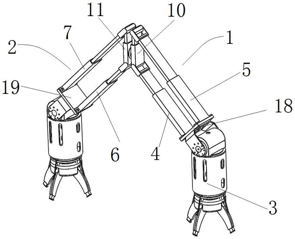
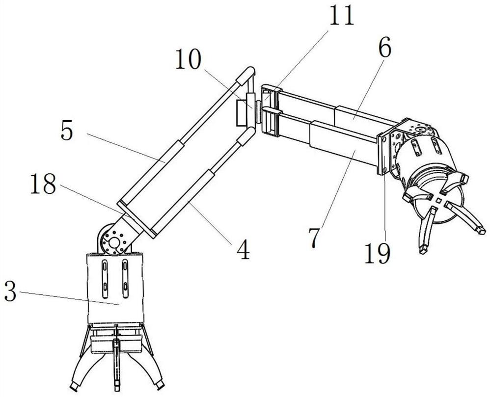
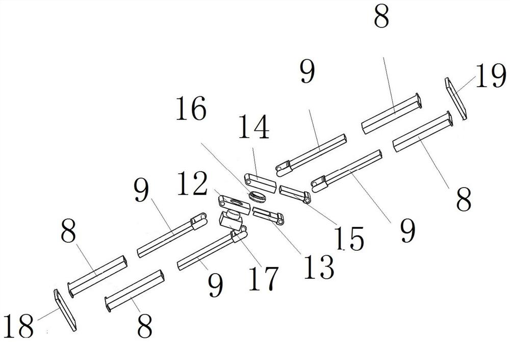
[0049] like Figure 1 to Figure 2 As shown, the bionic robot includes a first telescopic arm 1 and a second telescopic arm 2 that are rotatably assembled together. Both the first telescopic arm 1 and the second telescopic arm 2 include a drive telescopic rod that can be extended and retracted along the extension direction of the telescopic arm. The telescopic rods in the respective telescopic arms can be driven to extend and retract, not only can the distance of the telescopic arms be extended, but also the angle of the telescopic arms can be changed. By driving the expansion and contraction of the telescopic rod to cooperate with the swing of the two telescopic arms, the movement of the bionic robot with multiple postures is realized, so that the bionic robot in the present invention is suitable for various application scenarios. Wherein, each driving telescopic rod in the two telescopic arms is equipped with a telescopic driving mechanism, so that the telescopic driving of e...

specific Embodiment 2

[0061] The difference from Embodiment 1 is that in Embodiment 1, the rotating joint 16 is a cylindrical fitting structure. In this embodiment, the rotary joint includes bearings provided on the first connecting rod and the third connecting rod. Turn assembly.

specific Embodiment 3

[0063] The difference from Embodiment 1 is that in Embodiment 1, the cross-sections of the fixed rod 8 and the movable rod 9 are both rectangular, so that the fixed rod 8 and the movable rod 9 are guided to slide and prevent rotation. In this embodiment, the sections of the fixed rod and the movable rod are triangular. In other embodiments, the anti-rotation structure of other shapes such as pentagon and hexagon may also be used. In other different embodiments, the fixed rod and the movable rod are not required to stop rotation, and the fixed rod and the movable rod in this case may be cylindrical rods.


PUM


Abstract

The invention aims to provide the robot telescopic swing mechanism and the bionic robot to solve the technical problem that two arms of a bionic robot in the prior art can only swing in the same plane, so that the application range of the bionic robot is small. The bionic robot comprises a clamping jaw and further comprises a robot telescopic swing mechanism for driving the clamping jaw to adjust different poses, the robot telescopic swing mechanism comprises a first telescopic arm and a second telescopic arm, each telescopic arm comprises a base, and two driving telescopic rods are fixed to each base. Each driving telescopic rod comprises a fixed rod fixed to the base, a movable rod movably matched with the fixed rod in a guiding mode and a telescopic driving mechanism driving the movable rod to move, the first telescopic arm further comprises a first telescopic connecting rod, and the second telescopic arm further comprises a second telescopic connecting rod. And the first telescopic connecting rod and the second telescopic connecting rod are in running fit, and a rotation driving mechanism is arranged at the running fit position, so that the first telescopic arm and the second telescopic arm can rotate relatively.

Description

technical field [0001] The invention relates to the technical field of power machinery, in particular to a bionic robot capable of multi-angle telescopic and swinging. Background technique [0002] With the continuous exploration and progress in the field of power machinery technology, bionic robots, which have been improved and optimized, can replace human beings to complete more work. Among them, the ground mobile robot belongs to the focus of research in the field, including a bionic robot. The robot consists of three parts: a scalable platform, a parallel mechanism and a telescopic mechanism. It can imitate the raw telescopic forward process, and can be used to drill into narrow gaps. It can also change the size of the platform to enable the robot to move through the narrow gaps. Drill through gaps that are less than the width of the robot, expanding its task types. [0003] At present, relevant researchers in the field of mechanics at home and abroad have conducted in...

Claims


Application Information

Patent Timeline
Patent Type & Authority Applications(China)
IPC IPC(8): B25J18/02B25J9/12B25J15/10
CPCB25J18/025B25J9/12B25J15/10
Inventor 朱晓东姜晓东曾庆山司继凯彭金柱张方方
Owner ZHENGZHOU UNIV
Learn More