

Refrigeration system
A refrigeration system and condenser technology, applied in the field of capillary tubes
- Summary
- Abstract
- Description
- Claims
- Application Information
AI Technical Summary
Problems solved by technology
Method used
Image

Examples
Embodiment Construction
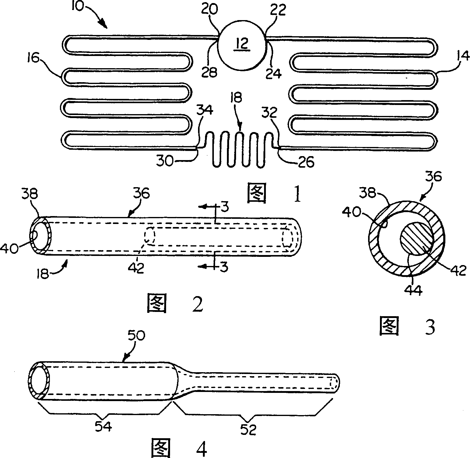
[0014] Figure 1 shows a refrigeration system 10 of the present invention. The refrigeration system 10 includes a compressor 12 connected to a condenser 14 and an evaporator 16 . The condenser 14 and evaporator 16 are connected by a capillary tube 18 of the present invention. During the refrigeration cycle, refrigerant flows from compressor 12 through condenser 14, capillary tubes 18, and into evaporator 16 where it is drawn back into compressor 12 to repeat the cycle.
[0015] As can be seen from a more detailed description of the refrigeration system 10, the compressor 12 has an air inlet 20 on its low pressure side, or vacuum side, and an air outlet 22 on its high pressure side. The condenser 14 has an air inlet 24 connected to the air outlet of the compressor and a condenser liquid outlet 26 . The evaporator has an evaporator gas outlet 28 connected to the compressor inlet 20 and an evaporator liquid inlet 30 . The capillary 18 has a liquid inlet 32 and a liquid outlet...
PUM
 Abstract
Description
Claims
Application Information