
Adjusting mechanism of drafting assembly of spinning frame

An adjustment mechanism and spinning frame technology, applied in spinning machines, drafting equipment, textiles and papermaking, etc., can solve the problems of time-consuming and laborious installation and operation, structure without adjustment, unfavorable use of spinning frames, etc., to achieve split The effect of simple structure and easy operation

Active Publication Date: 2022-08-05
永安市宝福纺织有限公司
View PDF9 Cites 0 Cited by
  • Summary
  • Abstract
  • Description
  • Claims
  • Application Information

AI Technical Summary

Problems solved by technology

[0004] The purpose of the present invention is to provide an adjustment mechanism for the drafting assembly of a spinning frame to solve the problem in the above-mentioned background technology that when the current spinning frame is drafting, it adopts an integrated fixed structure. Due to the high height, it is necessary to lift the person to the specified height, and then it is time-consuming and laborious to install and operate, which greatly affects the processing operation of the spinning frame. At the same time, when the rod body is drafted, the distance between the rod bodies is also fixed. Therefore, it does not have an adjustable structure, and it is not suitable for various drafting requirements, so it is not conducive to the use of the current spinning frame.

Method used


Image

  • Adjusting mechanism of drafting assembly of spinning frame
  • Adjusting mechanism of drafting assembly of spinning frame
  • Adjusting mechanism of drafting assembly of spinning frame

Examples


Embodiment Construction

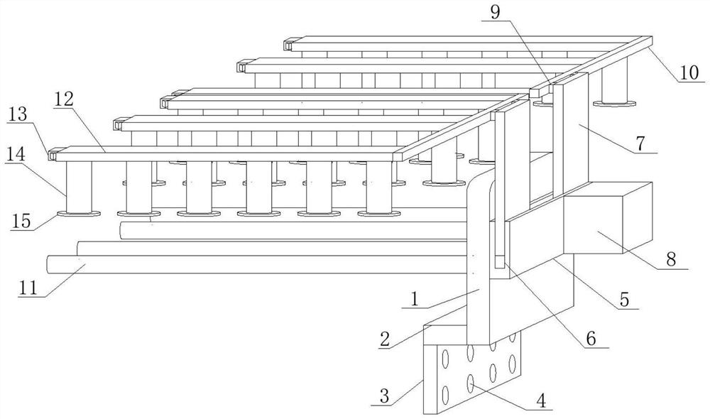
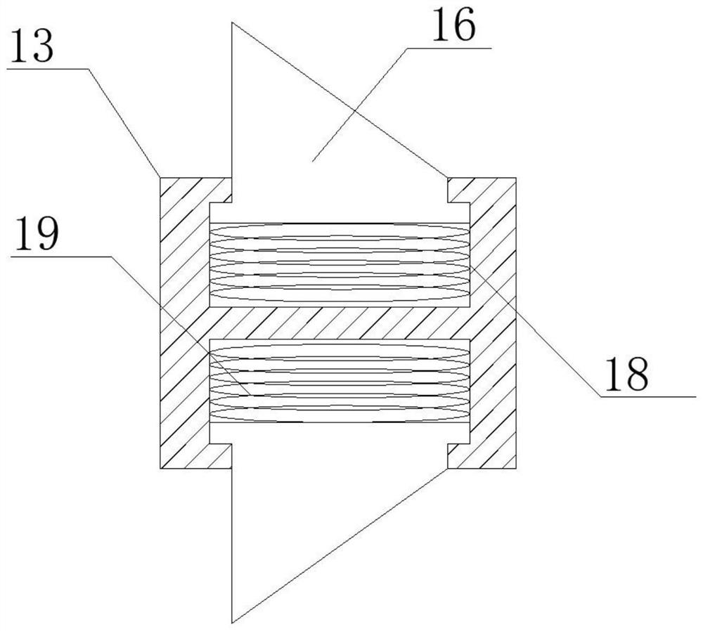
[0027] see Figure 1-2, In the embodiment of the present invention, an adjustment mechanism for a drafting assembly of a spinning frame includes a supporting side plate 1, the side of the supporting side plate 1 is vertically welded with a connecting cross plate 2, and the bottom surface of the connecting cross plate 2 is vertically downward welded with a Fixed connecting plate 3, fixed through holes 4 are evenly opened on the side of the fixed connecting plate 3, a side fixing block 5 is welded on one side of the supporting side plate 1, and one side of the connecting horizontal plate 2 is vertically fixed on the supporting side plate. The side of 1 is close to the bottom surface, the top of the fixed connecting plate 3 is vertically fixed at the position of the bottom surface of the connecting horizontal plate 2 away from the side of the supporting side plate 1, the number of fixed through holes 4 is multiple, and multiple fixed The through holes 4 are all open through the s...


PUM


Abstract

The invention discloses an adjusting mechanism for a drafting assembly of a spinning frame, and relates to the field of spinning frames, the adjusting mechanism comprises a supporting side plate, a connecting transverse plate is vertically welded to the side edge of the supporting side plate, a fixing connecting plate is vertically and downwards welded to the bottom surface of the connecting transverse plate, and fixing through holes are uniformly formed in the side edge of the fixing connecting plate; a side fixing block is welded to one side edge of the supporting side plate, an overturning groove channel is horizontally formed in the top face of the side fixing block, an overturning vertical rod is connected to the inner side edge of the overturning groove channel in an inserted mode, a fixing box body is connected to the side edge, away from the supporting side plate, of the side fixing block through a bolt, and end connecting blocks are perpendicularly welded to one side edge of the overturning vertical rod. A supporting transverse rod is welded to the end, away from the overturning vertical rod, of the end connecting block. The device is designed into a split structure and is simple and convenient to operate, multiple adjusting structures are adopted so that the device can be used and operated in various environments, and meanwhile, an assembled structure is adopted so that the device can be suitable for being used in cooperation with various devices.

Description

technical field [0001] The invention relates to the technical field of spinning frames, in particular to an adjustment mechanism for a drafting assembly of the spinning frames. Background technique [0002] Spinning frame, a spinning machine that draws, twists, and winds semi-finished rovings or slivers into spun bobbins during spinning The sliver is drafted and twisted to make spun yarn, the sliver is drafted and twisted on the roving frame to make roving, the comber combs the fiber to make the combed sliver, the needle card machine combines the sliver, and the needle row is drafted to improve the sliver structure and roving. The ring spinning frame is further twisted and spun into spun yarn. The spinning frame is the main machine for spinning, and the output and quality of the spun yarn are a comprehensive reflection of the advantages and disadvantages of each process in the spinning process. [0003] For the current spinning frame, it adopts an integrated fixed structure...

Claims


Application Information

Patent Timeline
Patent Type & Authority Applications(China)
IPC IPC(8): D01H5/22D01H5/44D01H13/00
CPCD01H5/22D01H5/44D01H13/00
Inventor 邓忠华曾志慧
Owner 永安市宝福纺织有限公司
Learn More