Sky curtain roof structure of building

A roof structure and building technology, applied in building structures, building components, buildings, etc., can solve the problem that solid ceilings and LED displays cannot achieve light transmission and ventilation, electronic sky curtains are highly decorative and practical, and cannot meet the needs of natural problems such as lighting and internal and external ventilation, to ensure the clarity and image quality, prevent indoor glare, and reduce indoor heat radiation.

Pending Publication Date: 2022-08-05
GUANGZHOU URBAN PLANNING & DESIGN SURVEY RES INST
View PDF7 Cites 0 Cited by
  • Summary
  • Abstract
  • Description
  • Claims
  • Application Information

AI Technical Summary

Problems solved by technology

[0006] In order to solve the above problems, the object of the present invention is to provide a sky screen roof structure of a building, to solve the problem that neither the solid ceiling nor the LED display screen can play the role of light transmission and ventilation, which has caused the existing electronic sky screen to be more decorative than practical. Inability to meet the requirements of natural lighting and internal and external ventilation

Method used


Image

  • Sky curtain roof structure of building
  • Sky curtain roof structure of building
  • Sky curtain roof structure of building

Examples


Embodiment Construction

[0035] The specific embodiments of the present invention will be described in further detail below with reference to the accompanying drawings and embodiments. The following examples are intended to illustrate the present invention, but not to limit the scope of the present invention.

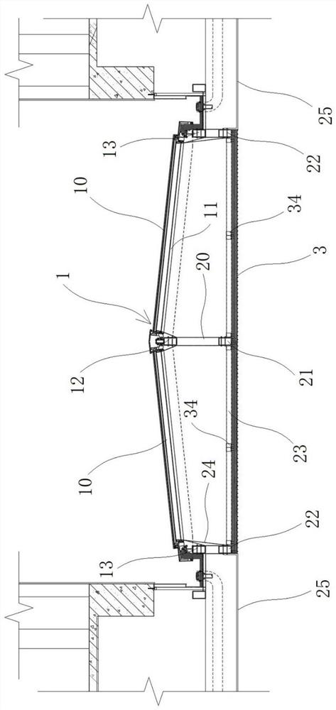
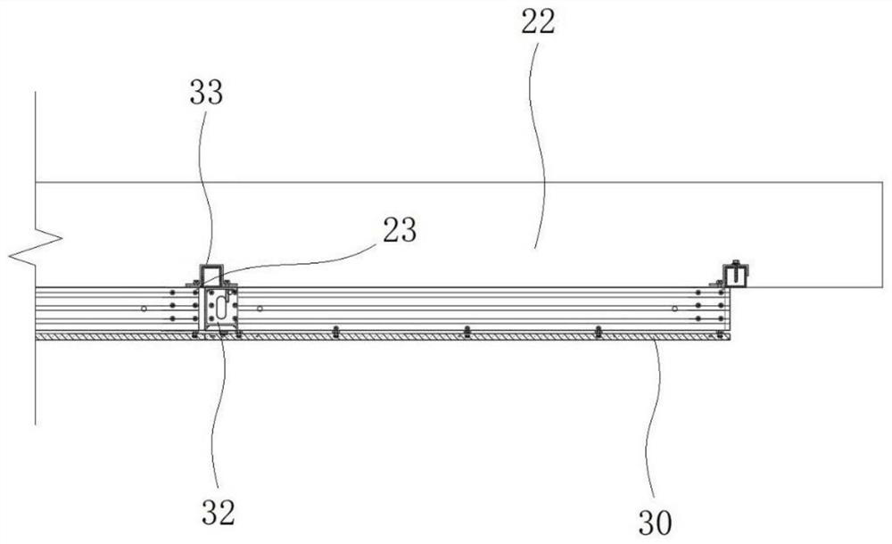
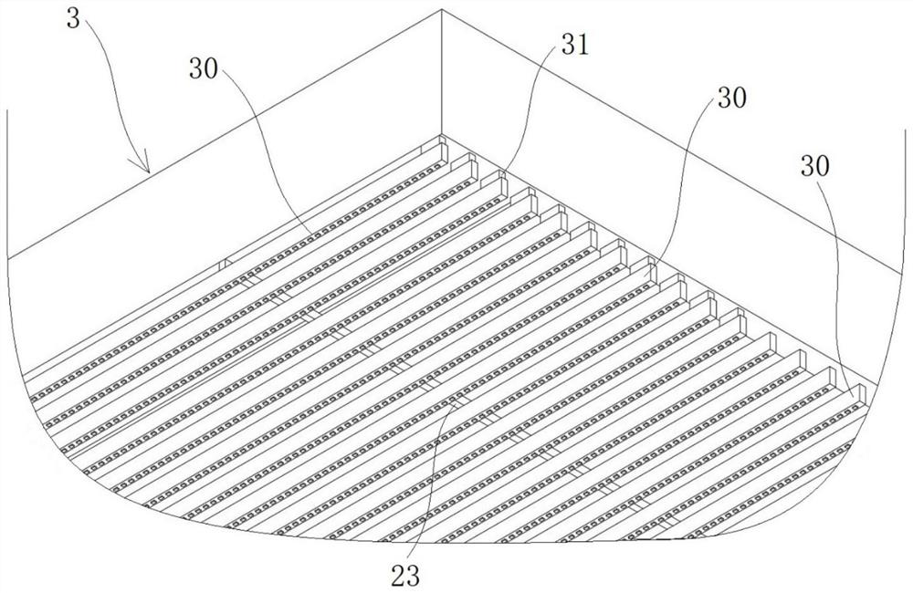
[0036] The specific embodiment 1 of the canopy roof structure of the building of the present invention, such as Figure 1 to Figure 7 As shown, the skylight roof structure of the building includes a skylight structure 1, a skylight frame 2 and an electronic skylight 3, the skylight structure 1 is arranged on the upper side of the patio of the building, and the skylight structure 1 has an open state and a closed state. The inside and outside of the building are ventilated; the inner side of the skylight structure 1 is provided with a shading curtain 11, which is movably connected with the skylight structure 1 to adjust the retraction or unfolding of the shading curtain 11; the skylight frame 2 i...


PUM


Abstract

The invention provides a sky curtain roof structure of a building, and relates to the field of electronic sky curtains. The sky curtain roof structure of the building comprises a skylight structure, a sky curtain frame and an electronic sky curtain, the skylight structure is arranged at a courtyard of the building, and when the skylight structure is opened, internal and external ventilation of the building can be achieved; a window shade is installed on the inner side of the skylight structure and movably connected with the skylight structure so that the window shade can be adjusted to be folded or unfolded. The skyscreen frame is fixed on the lower side of the skylight structure, the skyscreen frame is composed of metal rods, a hollow area is arranged in the skyscreen frame, and the electronic skyscreen is installed on the lower side of the skyscreen frame; the electronic backdrop comprises a plurality of light-emitting lamp strips which are arranged side by side at intervals, ventilation and lighting intervals are formed between the adjacent light-emitting lamp strips, and the skylight structure, the hollow area of the backdrop frame and the ventilation and lighting intervals of the electronic backdrop are communicated up and down to form a ventilation and light-transmitting channel. The sky curtain roof structure integrates the decoration and practicability of the electronic sky curtain, and meets the requirements of natural lighting and internal and external ventilation.

Description

technical field [0001] The invention relates to the technical field of electronic sky screens, in particular to a sky screen roof structure of a building. Background technique [0002] With the rapid development of optoelectronic technology, the design of installing electronic canopies on the ceiling of buildings has emerged. Electronic canopies usually use LED displays to embellish the space and render the atmosphere. [0003] For example, the Chinese invention patent application with the application publication number CN111561097A and the application publication date of 2020.08.21 discloses an integral luminous ceiling, which specifically includes a number of light panels arranged horizontally directly below the indoor roof, and the frontal intervals of each light panel are evenly distributed There are a plurality of light board LED lamp beads that can be controlled to emit light. The light board and a number of light board LED light beads are combined to form a light boar...

Claims


Application Information

Patent Timeline
Patent Type & Authority Applications(China)
IPC IPC(8): E04D13/03E04D13/035E04B9/00G09F9/33
CPCE04D13/03E04D13/031E04D13/0325E04D13/033E04D13/0351E04B9/006G09F9/33E04D2013/034Y02B10/10
Inventor 胡展鸿周巧
Owner GUANGZHOU URBAN PLANNING & DESIGN SURVEY RES INST
Why Eureka
Try Eureka