Magnetic type wire fixing device

A wire-fixing and magnetic-suction technology, which is applied to electrical components and other directions, can solve the problems of not being able to fix the cable, the tie is falling off, and the wiring is difficult, so as to achieve the effect of convenient wiring and convenient assembly.

Pending Publication Date: 2022-08-05
LUOYANG PUFAN ELECTRIC AUTOMATION
View PDF0 Cites 0 Cited by
  • Summary
  • Abstract
  • Description
  • Claims
  • Application Information

AI Technical Summary

Problems solved by technology

This has caused a lot of difficulties in wiring the detection devices on the host. On the one hand, the cables must be fixed, and on the other hand, the cables cannot be fixed on the host equipment such as oil pipes.
[0003] (1) Nylon cable ties are used to tie the wires at present. The wires must be tied to some equipment. When tying the wires, they must be extended on some equipment. Looks good, after a period of use, the nylon cable tie oxidizes and becomes brittle, causing the cable tie to fall off
[0004] (2) At present, the wire fixing method of the sensor near the hoist brake disc is to tie the wire of the sensor to the oil pipe with a wire tie. Once the cable leaks, the host equipment will run with electricity
[0005] (3) At present, the wire fixing method of the sensor near the brake disc of the hoist is to tie the wire of the sensor to the oil pipe with a wire tie. Once the cable leaks, it is easy to cause the oil circuit on the oil pipe to catch fire.
[0006] (4) Use nylon cable ties to fix the wires. Once you are not satisfied with the wiring, you must cut the cable ties and re-tie the wires, which is a waste of time and is not environmentally friendly.

Method used


Image

  • Magnetic type wire fixing device
  • Magnetic type wire fixing device

Examples


Embodiment Construction

[0018] The present invention will be further described below in conjunction with the accompanying drawings.

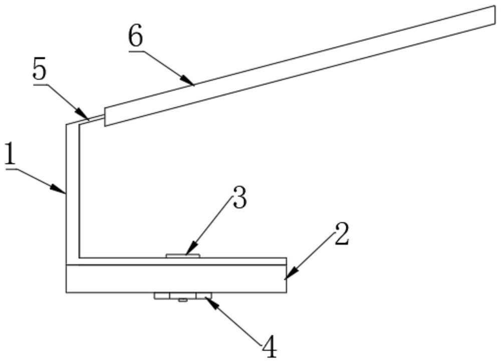
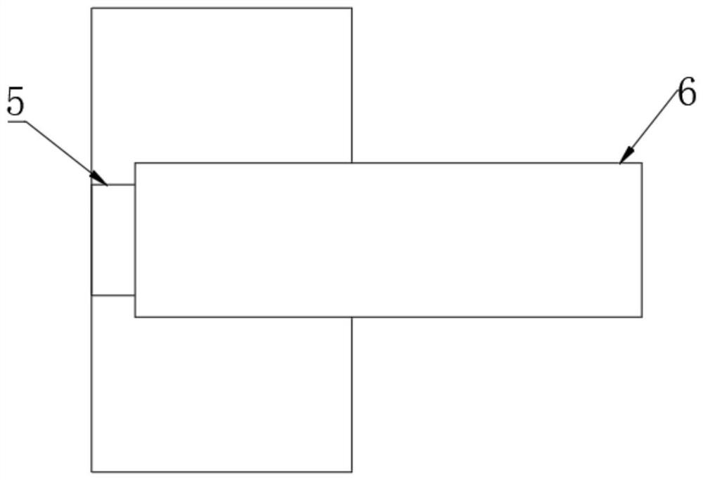
[0019] A magnetic wire fixer, comprising a wire fixer body 1, a magnet 2, a metal shrapnel, a screw 3, and a nut 4, is characterized in that: a magnet 2 is adsorbed on the outer surface of the fixer body 1, and the magnet 2 is A square magnet, the wire fixer body 1 and the square magnet 2 are both provided with threaded holes, the square magnet 2 and the metal shrapnel are fixed with screws 3 and nuts 5, and the metal shrapnel has a retaining spring 5, which can The cable is fixed in the middle of the clip, and the outer wall of the clip spring 5 is sleeved with a plastic sheath 6 .

[0020] The mounting position of the nut 5 and the screw 4 is set at the lower end of the square magnet 2 .

[0021] During the specific implementation of the present invention,

[0022] The present invention uses the magnet 2 and the metal shrapnel 4 to make a magnetic wire fixing devic...


PUM


Abstract

The invention relates to the technical field of cable fixing devices, in particular to a magnetic type cable fixing device, which comprises a cable fixing device body, a magnet, a metal elastic sheet, a screw and a nut, and is characterized in that the magnet is adsorbed on the outer surface of the cable fixing device body, the magnet is a square magnet, threaded holes are formed in the cable fixing device body and the square magnet, and the threaded holes are communicated with the screw. The square magnet and the metal elastic piece are fixed through a screw and a nut, the metal elastic piece is provided with a clamping spring, a cable can be fixed to the middle of a buckle, and the outer wall of the clamping spring is sleeved with a plastic sheath. 2, on-site wiring is convenient, and adjustment can be made at any time according to on-site conditions; 3, the requirement of oil-electricity separation can be met; the cable is fixed through magnetism, and durability is achieved.

Description

technical field [0001] The invention relates to the technical field of cable fixing devices, in particular to a magnetic suction type cable fixing device. Background technique [0002] When fixing the wires and cables in the "Coal Mine Safety Regulations" currently followed by the mines, it is not allowed to bundle the wires and cables with the oil pipe. This makes it difficult to route many detection devices on the host computer. On the one hand, the cables cannot be fixed, and on the other hand, the cables cannot be fixed on the host equipment such as oil pipes. [0003] (1) The current cable tie uses nylon cable ties, which must be tied to certain equipment. When tying the cable, it must be extended to some equipment, which is inconvenient to route the cable, and the line type that comes out is not Good-looking, after a period of use, the nylon cable ties oxidize and become brittle, causing the cable ties to fall off. [0004] (2) The current method of fixing the sensor...

Claims


Application Information

Patent Timeline
Patent Type & Authority Applications(China)
IPC IPC(8): H02G3/02
CPCH02G3/02
Inventor 刘华卫申凯张成闫帅东魏三统席挺
Owner LUOYANG PUFAN ELECTRIC AUTOMATION
Why Eureka
Try Eureka