Emergency mobile multifunctional power van

A power vehicle and multi-functional technology, applied in the field of power vehicles, can solve problems such as affecting device action, reducing service life, and surrounding dangers, achieving the effects of reducing forward resistance, improving convenience of use, and reducing floor space

Pending Publication Date: 2022-08-05
深圳市门罗智能有限公司
View PDF0 Cites 0 Cited by
  • Summary
  • Abstract
  • Description
  • Claims
  • Application Information

AI Technical Summary

Problems solved by technology

[0003] Some problems still exist in the existing device: 1. When the device is in use, it often encounters some bad weather and environment. The rain, snow and garbage on the road will cause obstacles when the vehicle is moving forward, affecting the action of the device; 2. When supplying power, the distance between the device and the power transmission destination is often too far, resulting in the need to use an external terminal board to

Method used


Image

  • Emergency mobile multifunctional power van
  • Emergency mobile multifunctional power van
  • Emergency mobile multifunctional power van

Examples


Example Embodiment

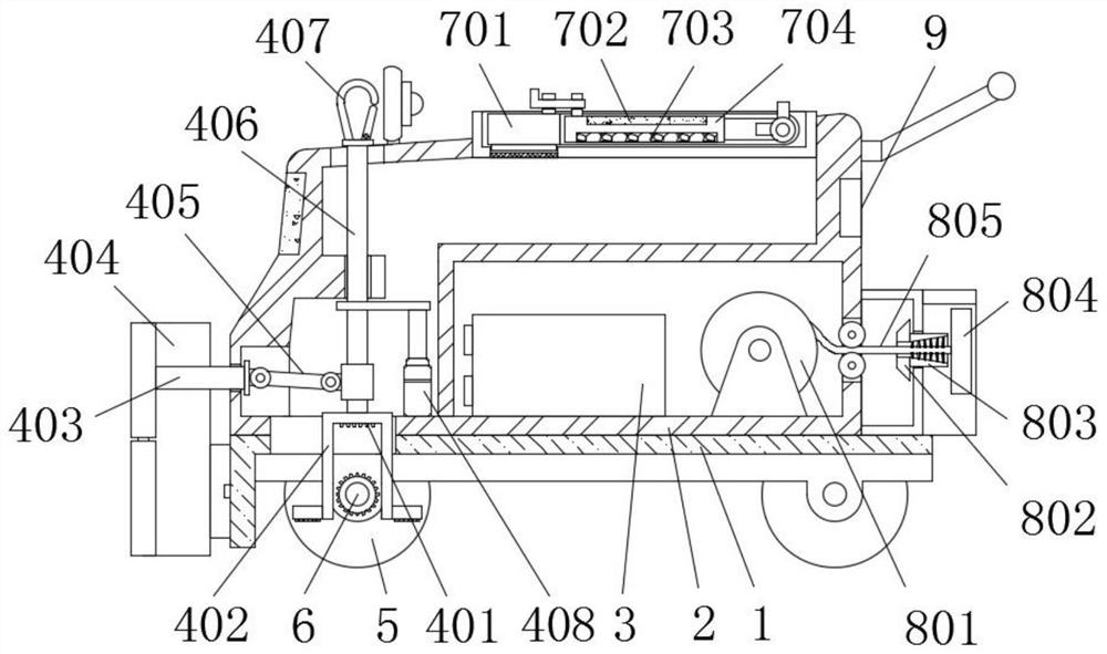
[0039] Example 1, as figure 1 , 4 As shown in , 5 and 6, after the device moves to the designated position, the movable rod 406 is controlled by the electric push rod 408 to descend, which can drive the safety lock 402 to move down, so that after the locking teeth 401 are engaged with the fixed gear 409, the rod can be reversed. 6 is restricted to prevent the moving wheel 5 from moving, so that the device can be parked more safely. At the same time, the anti-skid pad on the safety lock 402 can be attached to the ground, which improves the friction between the device and the ground and strengthens the parking stability.

Example Embodiment

[0040] Example 2, as figure 1 and 5 As shown in the figure, when the device transmits power over a long distance and needs to stow up the drag line 804, the motor 807 can be started, and the reel 801 can be driven by the motor 807 to rotate to rewind the wire 805, and when the reel 801 rotates , which can drive a set of pulleys 808 to rotate, and then the belt 809 can drive another set of pulleys 808 to rotate, so that the bevel gear B810 rotates, and the bevel gear B810 can drive the meshing bevel gear A802 to rotate, so that the cleaning brush 803 can rotate. Rotate and brush the wire 805 during winding to remove the dust on its surface.

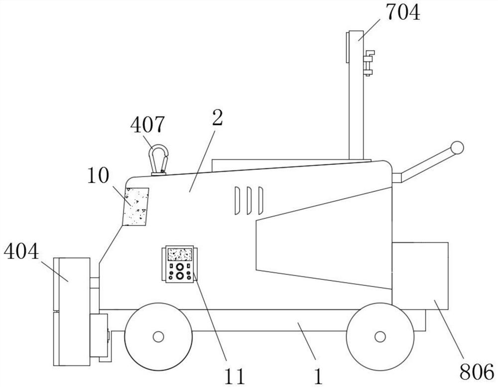
[0041] Working principle: when the device needs to move, the electric push rod 408 is first activated, and the movable rod 406 can be pushed up by the electric push rod 408, so that the safety lock 402 can be raised, and the restriction of the rotation rod 6 is lifted. At this time, the movable rod 406 The clearing board 404 can be pushe...


PUM


Abstract

The emergency mobile multifunctional power van comprises a base, a waterproof and dustproof shell is arranged at the top of the base, a lithium battery pack is arranged in the middle of the bottom of the interior of the waterproof and dustproof shell, the two sides of the bottom of the base are sleeved with rotating rods, and moving wheels are arranged at the two ends of the two rotating rods; the top of one side of the waterproof and dustproof shell is provided with a power plug board, the top of the other side of the waterproof and dustproof shell is provided with an electric quantity display screen, and one side of one end of the waterproof and dustproof shell is provided with an emergency stop switch. Through mutual cooperation of clamping teeth, a safety lock, a connecting rod, a barrier removing plate, a hinge rod, a movable rod, a lock hook, an electric push rod, a fixed gear, a moving wheel and a rotating rod, when the device moves, the barrier removing plate can be unfolded to form a cone, two-side flow guiding is conducted on front barriers, the forward resistance of the device is reduced, and the device can be used in various severe environments.

Description

technical field [0001] The invention relates to the technical field of power supply vehicles, in particular to an emergency mobile multifunctional power supply vehicle. Background technique [0002] With the needs of national construction and development, special-purpose vehicles have become important transportation and operation equipment in economic construction, and will have good development prospects. A live emergency work vehicle designed for the needs of the emergency, which can be used for emergency repairs and power supply caused by emergencies, and plays a very important role. [0003] There are still some problems in the existing device: 1. When the device is used, it often encounters some bad weather and environment, and the rain, snow and garbage on the road will cause obstacles when the vehicle is moving forward, affecting the operation of the device; 2. During the process When supplying power, the distance between the device and the transmission destination i...

Claims


Application Information

Patent Timeline
IPC IPC(8): H02J9/00B60P3/00B60R19/54B65H75/44B65H75/42B08B1/02
CPCH02J9/00B60P3/00B60R19/54B65H75/4486B65H75/425B08B1/02B65H2701/34Y02T10/7072
Inventor 肖明刘辉何亮雷宇
Owner 深圳市门罗智能有限公司
Why Eureka
Try Eureka