Air bubble pad decompression boat

A bubble pad and hull technology, applied in the field of electromechanical, can solve the problems of increasing the overall weight of the power supply system, increasing the failure rate, complex structure, etc., and achieve the effect of increasing the traveling speed, reducing the transportation cost and reducing the forward resistance.

Inactive Publication Date: 2007-10-10
杨天君
View PDF0 Cites 5 Cited by
  • Summary
  • Abstract
  • Description
  • Claims
  • Application Information

AI Technical Summary

Problems solved by technology

[0003] The purpose of the present invention is to provide a bubble cushion decompression ship, which solves the problems of large power consumption of the existing ship, increased overall weight of the power supply system, complex structure, increased failure rate, and increased cost.

Method used


Image

  • Air bubble pad decompression boat
  • Air bubble pad decompression boat

Examples


Embodiment Construction

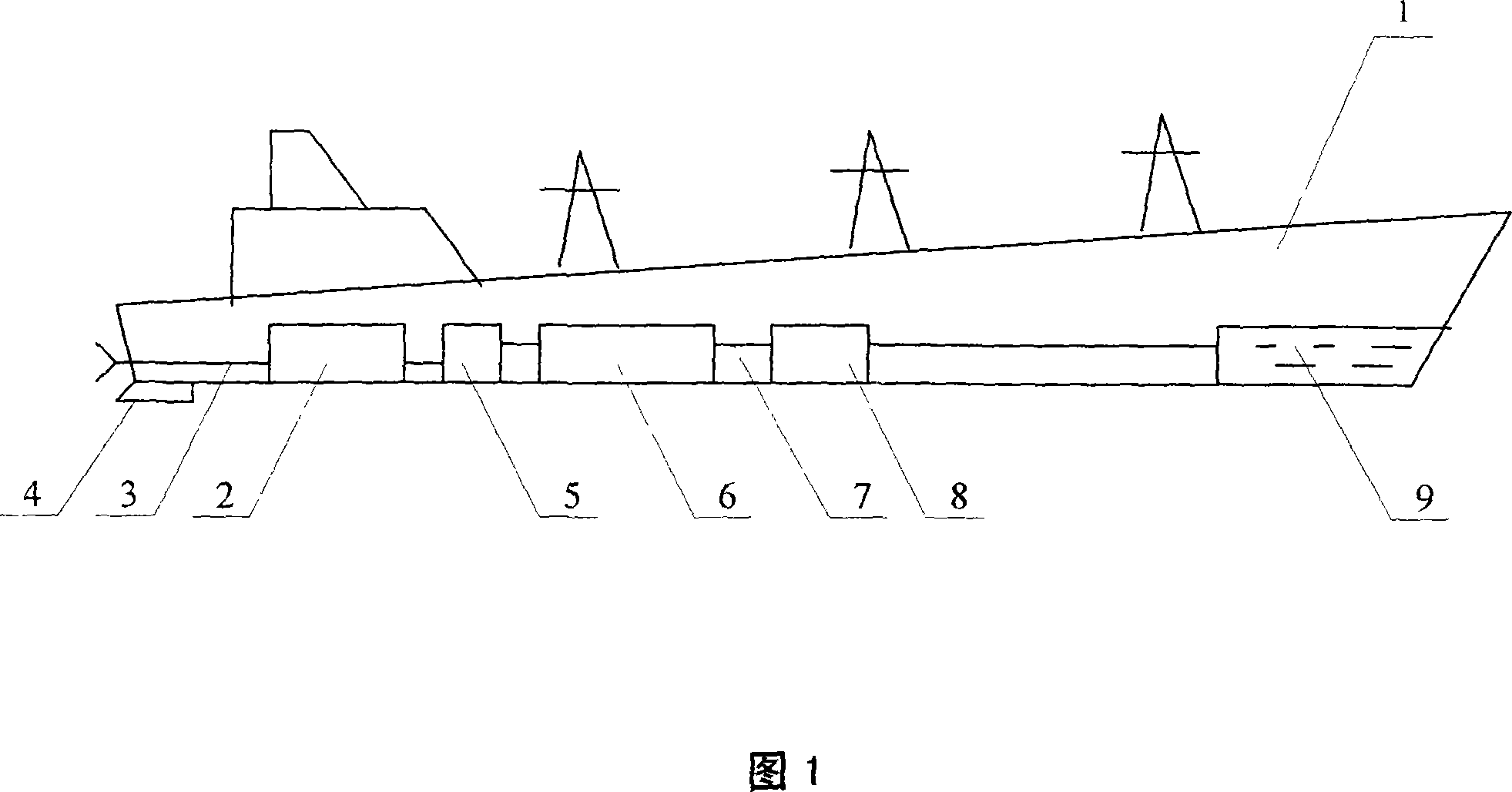
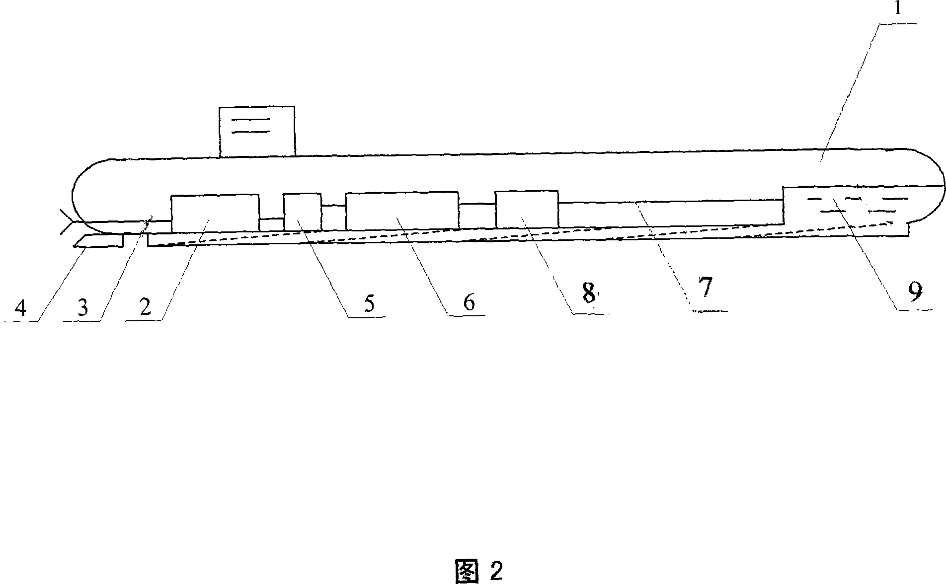
[0009] As shown in accompanying drawing 1, the present invention is made up of hull 1, engine 2, drive system 3, direction control system 4, air blower 5, air storage tank 6, air supply pipe 7, air supply controller 8, bubble generation device 9, Wherein, engine 2, drive system 3 and direction control system 4 are provided at the stern of hull 1; blower 5 is provided at the front of engine 2, and blower 5 is connected with air storage tank 6 through air supply pipe 7, and air storage tank 6 passes through The air supply pipe 7 is connected with the air supply controller 8, and the air supply controller 8 is connected with the bubble generating device 9 through the air supply pipe 7;

[0010] When the ship is moving, the blower 5 delivers compressed air to the air storage tank 6 through the air supply pipe 7, and then adjusts the air supply volume by the air supply controller 8, and delivers compressed air to the air bubble generating device 9 through the air supply pipe 7, and ...


PUM


Abstract

A ship able to generate an air bubble cushion to decrease water resistance is composed of ship body, engine, drive system, direction control system, blowers, compressed air tanks, air feeding tubes and their controller, and air bubble generators.

Description

technical field [0001] The invention relates to electromechanical devices, in particular to a bubble cushion decompression ship. Background technique [0002] As we all know, a ship is a common means of transportation in the nautical field. The existing ship is composed of a hull, a drive system and a direction control system. Because the pressure of water on the bow and the drainage resistance of the ship are very large when the ship is moving, the speed of the existing ship is relatively slow, and the power consumption is relatively large, so that the overall weight of the power supply system is increased, the structure is complicated, and the failure rate is increased. , cost increase, these many deficiencies, urgently need to be improved. Contents of the invention [0003] The purpose of the present invention is to provide a bubble cushion decompression ship, which solves the problems of the existing ships such as large power consumption, increased overall weight of t...

Claims


Application Information

Patent Timeline
Patent Type & Authority Applications(China)
IPC IPC(8): B63B1/38
CPCY02T70/122Y02T70/10
Inventor 杨天君
Owner 杨天君
Why Eureka
Try Eureka