Delivery system for atrial shunt

A delivery system and shunt technology, applied in the field of medical devices, can solve problems such as the complex composition of delivery devices, achieve the effects of reducing complexity, refining and saving, and improving acceptance speed

Pending Publication Date: 2022-08-09
CHENXING (NANTONG) MEDICAL EQUIP CO LTD
View PDF0 Cites 0 Cited by
  • Summary
  • Abstract
  • Description
  • Claims
  • Application Information

AI Technical Summary

Problems solved by technology

However, the composition of delivery devices specially used for atrial shunts on the market is too complicated, which causes a large economic burden on patients and their families. Therefore, it is necessary to develop an implantable atrial shunt with rich functions, simple operation, and saving operation time. device, benefiting patients and their families

Method used


Image

  • Delivery system for atrial shunt
  • Delivery system for atrial shunt
  • Delivery system for atrial shunt

Examples


Embodiment Construction

[0049] The embodiments of the present invention are described below through specific specific examples, and those skilled in the art can easily understand other advantages and effects of the present invention from the contents disclosed in this specification. The present invention can also be implemented or applied through other different specific embodiments, and various details in this specification can also be modified or changed based on different viewpoints and applications without departing from the spirit of the present invention. It should be noted that the following embodiments and features in the embodiments may be combined with each other under the condition of no conflict.

[0050] The purpose of the present invention is to provide a delivery system for an atrial shunt in view of the defects of the prior art.

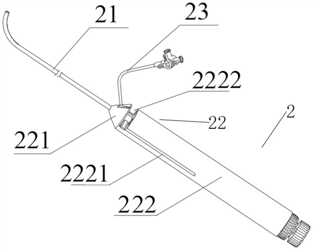
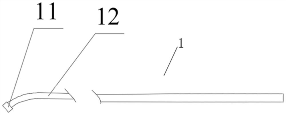
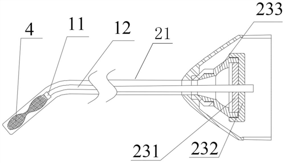
[0051] An embodiment of the delivery system for an atrial shunt provided by the present invention, such as Figure 1-22 As shown, it includes a loading str...


PUM


Abstract

The invention discloses a conveying system for an atrial shunt. The conveying system comprises a conveying structure and a control structure for controlling the axial movement of the conveying structure, the conveying structure comprises a conveying sheathing canal and a pushing rod penetrating through the conveying sheathing canal; the control structure comprises a control part and a conduction part which are connected with each other; the far end of the conduction part is connected with the pushing rod, the control part is rotated to drive the conduction part to move, and then the conduction part drives the pushing rod to move along a channel formed by the conveying sheath tube. The loading, conveying and releasing functions of a traditional atrial shunt conveying device are integrated on one handle, the complexity of the device is reduced, operation is easy, and the receiving speed of a doctor to the device is increased. Finally, the control structure is divided into the first control part and the second control part, and the requirements for refinement and operation time saving in actual operation are flexibly met.

Description

technical field [0001] The present invention relates to the technical field of medical devices, in particular to a delivery system for an atrial shunt. Background technique [0002] Heart failure (HF) for short , resulting in cardiac circulatory disorder syndrome, which is manifested as pulmonary congestion and vena cava congestion in this disorder syndrome. [0003] According to the location of heart failure, it can be divided into: (1) Left heart failure: refers to heart failure caused by left ventricular compensatory insufficiency, which is relatively common clinically and is characterized by pulmonary circulation congestion; (2) Right heart failure: simple Right heart failure is mainly seen in pulmonary heart disease and some congenital heart disease, and is mainly characterized by systemic congestion; (3) Whole heart failure: after left heart failure, the pulmonary artery pressure increases, which increases the load on the right heart. Right heart failure also occ...

Claims


Application Information

Patent Timeline
Patent Type & Authority Applications(China)
IPC IPC(8): A61B17/00A61F2/24
CPCA61B17/00234A61F2/2493A61F2/2436A61F2/2466A61B2017/00243
Inventor 熊忠亮姜程文梁玉晨
Owner CHENXING (NANTONG) MEDICAL EQUIP CO LTD
Why Eureka
Try Eureka