Straight-flow water gun mounting structure for fire fighting truck
An installation structure and direct-flow water technology, which is applied in fire rescue and other fields, can solve the problems of unfavorable promotion and use, lack of water gun head placement, and large space occupation
- Summary
- Abstract
- Description
- Claims
- Application Information
AI Technical Summary
Problems solved by technology
Method used
Image
Examples
Embodiment 1
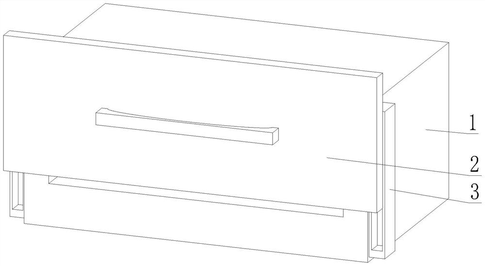
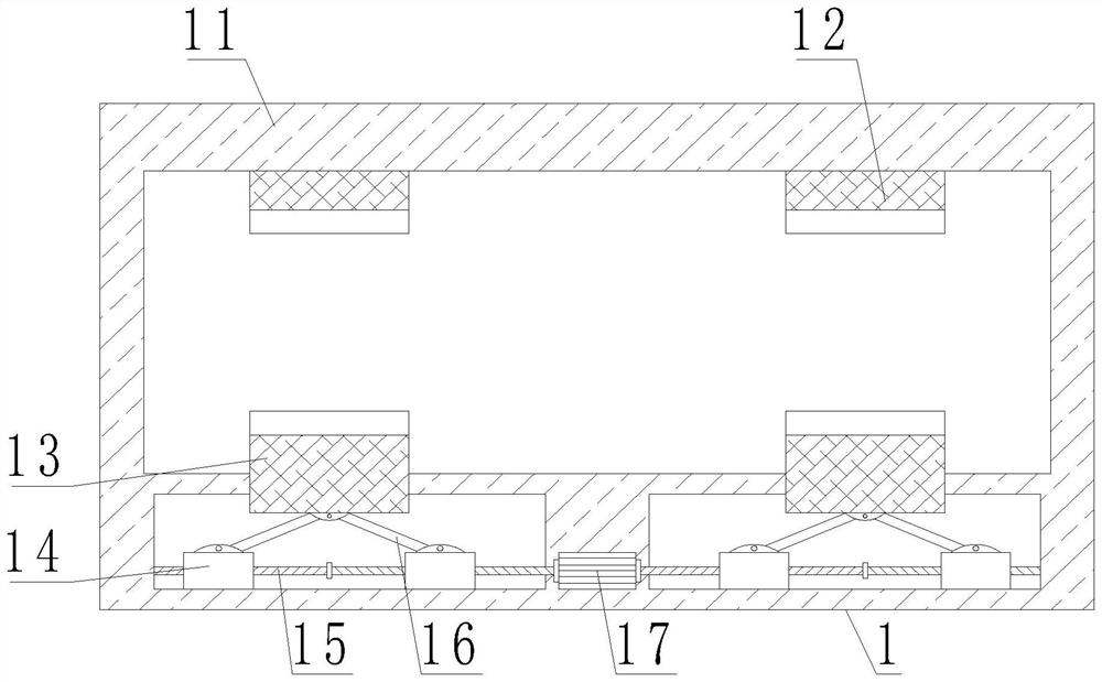
[0042] like Figure 1-9 As shown, the present invention provides an installation structure of a direct current water gun for a fire truck, including an installation structure 1, a fixing mechanism 3 is arranged on the side of the installation structure 1, and the installation structure 1 includes an outer mounting frame 11, and the interior of the outer mounting frame 11 is provided with In the drive slot, a double-headed motor 17 is arranged inside the installation frame 11. The output end of the double-headed motor 17 is fixedly connected with a rotating threaded rod 15, and the other end of the rotating threaded rod 15 is movably connected with the inner wall of the driving groove. A displacement threaded block 14 is threadedly connected to the surface of the outer frame 14, a connecting rod 16 is movably connected to the top of the displacement threaded block 14, the other end of the connecting rod 16 is movably connected to a gun head placing plate 13, and a gun head is fi...
Embodiment 2
[0045] like Figure 1-9 As shown, on the basis of Embodiment 1, the present invention provides a technical solution: preferably, the fixing mechanism 3 includes a fixing housing 31, and a limiting groove is set in the interior of the fixing housing 31, and the inner wall of the limiting groove is movably connected with a limiting block 37. The surface of the limit block 37 extends to the inner cavity of the fixed casing 31 and is fixedly connected with a lifting block 32, the inner cavity of the lifting block 32 is filled with a soft rebound bag 33, and the surface of the soft rebound bag 33 is overlapped with a displacement plate 34. , the surface of the displacement plate 34 is fixedly connected with a connecting column 35 , and the surface of the connecting column 35 is fixedly connected with a contact block 36 .
[0046] In this embodiment, the limit block 37 can only be displaced in the limit groove, so as to ensure the displacement stability of the lift block 32 , and no...
Embodiment 3
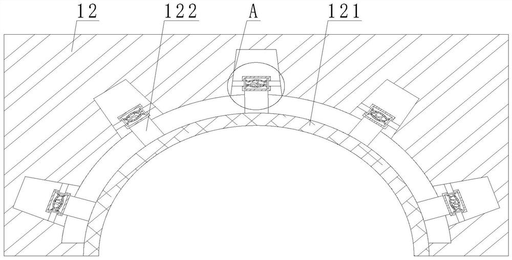
[0048] like Figure 1-9 As shown, on the basis of Embodiment 1, the present invention provides a technical solution: preferably, a buffer groove is provided inside the contact plate 12 of the gun head, the inner wall of the buffer groove is overlapped with an inclined block 123, and the surface of the inclined block 123 A movable plate 124 is fixedly connected, a movable shell 125 is movably connected to the surface of the inclined block 123 and the movable plate 124, an elastic shell 126 is fixedly connected to the surface of the movable shell 125, and the interior of the elastic shell 126 is filled with an elastic soft bag 127, and the movable shell 125 A fixed column 122 is fixedly connected to the surface, an elastic pad 121 is fixedly connected to the surface of the fixed column 122, the elastic pad 121 is fixedly connected to the surface of the contact plate 12 of the gun head, and the inner cavity of the elastic pad 121 is fixedly connected with a cross elastic sheet 121...
PUM
 Abstract
Description
Claims
Application Information
 - R&D
- Intellectual Property
- Life Sciences
- Materials
- Tech Scout
- Unparalleled Data Quality
- Higher Quality Content
- 60% Fewer Hallucinations
Browse by: Latest US Patents, China's latest patents, Technical Efficacy Thesaurus, Application Domain, Technology Topic, Popular Technical Reports.
© 2025 PatSnap. All rights reserved.Legal|Privacy policy|Modern Slavery Act Transparency Statement|Sitemap|About US| Contact US: help@patsnap.com


