
Bone continuing device for clinical fracture in orthopedics department

A bone continuation and orthopedics technology, applied in the field of bone continuation devices, can solve the problems of patients with low limit strength, limited upper limb fixation strength, secondary injury of fracture parts, etc., and achieves improvement of surface roughness, softness, and connection strength. Effect

Pending Publication Date: 2022-05-17
LUOYANG ORTHOPEDIC TRAUMATOLOGICAL HOSPITAL
View PDF0 Cites 0 Cited by
  • Summary
  • Abstract
  • Description
  • Claims
  • Application Information

AI Technical Summary

Problems solved by technology

[0004] The purpose of the present invention is to solve the limitations of the traditional bone extension device in the prior art for patients of different age groups and upper limbs with different thicknesses, and the fixation strength of the upper limbs is limited. When the fixation is performed first, the limiting strength is low and easy Due to the disadvantage of causing secondary injury to the patient's fracture site, a bone extension device for clinical fractures in orthopedics is proposed

Method used


Image

  • Bone continuing device for clinical fracture in orthopedics department
  • Bone continuing device for clinical fracture in orthopedics department
  • Bone continuing device for clinical fracture in orthopedics department

Examples


Embodiment 1

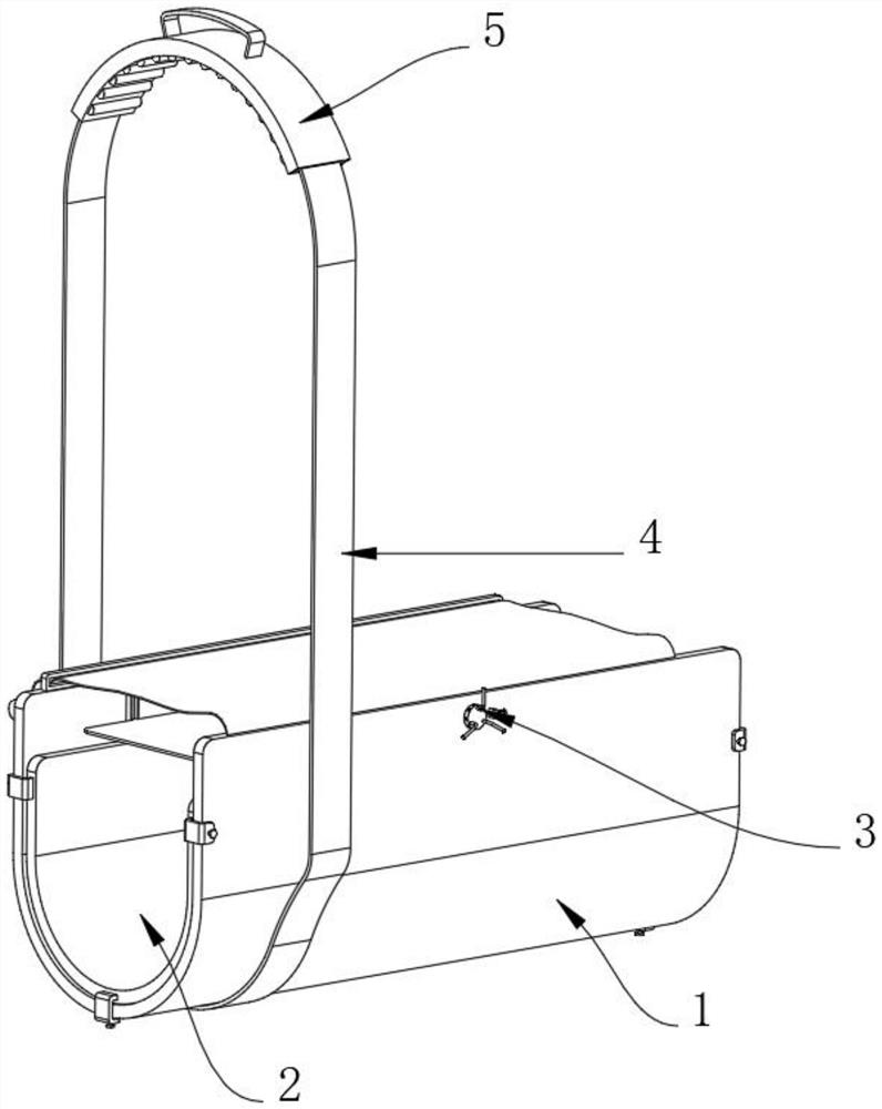
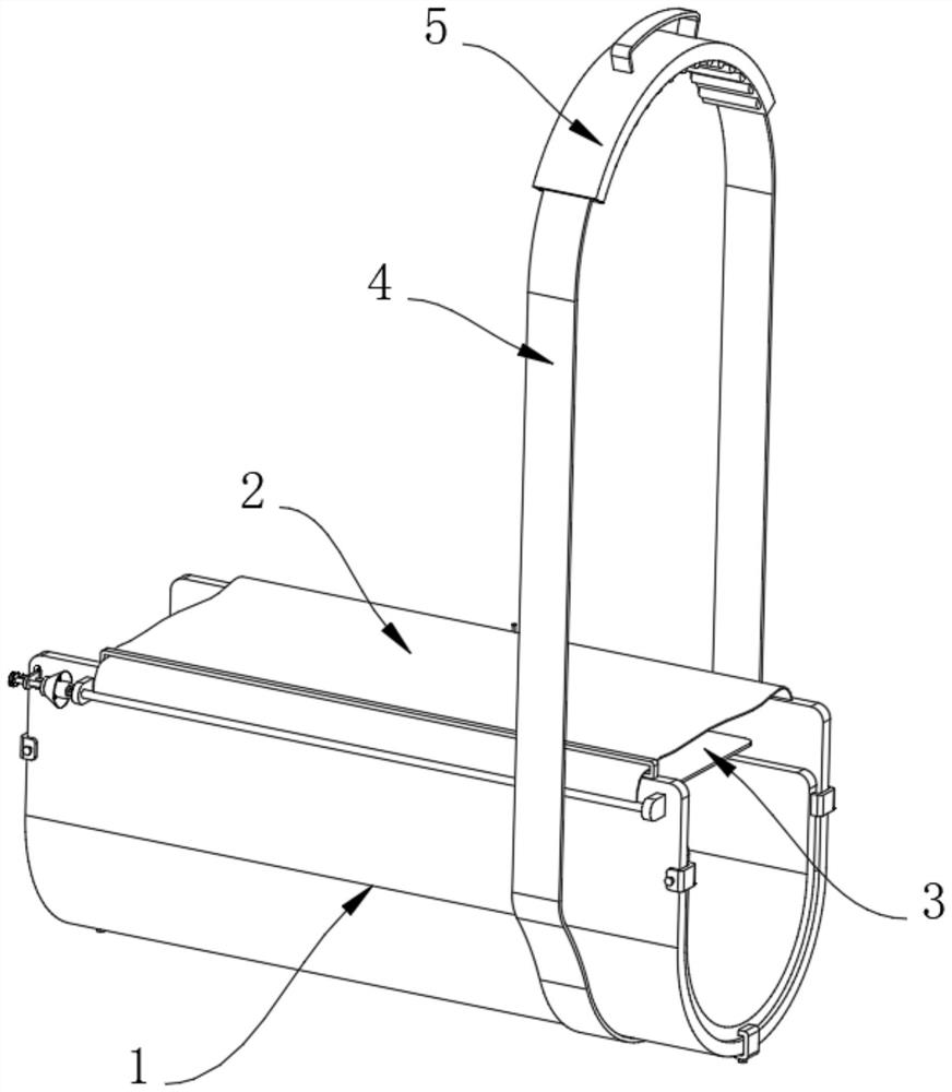
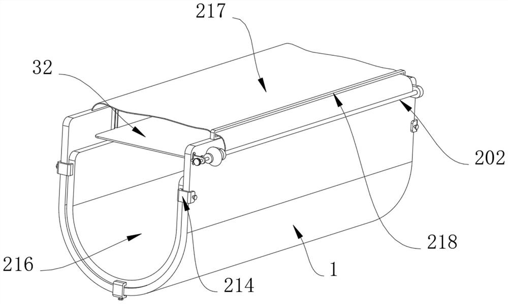
[0045] Example 1, such as Figure 1-12 As shown, the present invention provides a bone extension device for orthopedic clinical fractures, comprising an elastic splint 1 and a limiting structure 2, the arc surface of the elastic splint 1 is fixedly connected with a lanyard 4, and one side of the elastic splint 1 is provided with a limiter Structure 2, the inner side of the elastic splint 1 is provided with an adjustment structure 3, and the surface of the lanyard 4 is provided with an auxiliary structure 5.

[0046] Let's talk about the specific setting and function of its position-limiting structure 2, regulating structure 3 and auxiliary structure 5 in detail below.

[0047] Such as Figure 4 with Figure 5 As shown, the limiting structure 2 includes two fixed blocks 201, both fixed blocks 201 are fixedly connected to one side of the elastic splint 1, the two fixed blocks 201 are rotatably connected with a rotating shaft 202, and the arc surface of the rotating shaft 202 i...

Embodiment 2

[0051] Embodiment 2, on the basis of embodiment 1, as Figure 11 with Figure 12 As shown, the auxiliary structure 5 includes a sheath 51, the sheath 51 is set on the surface of the lanyard 4, the two ends of the sheath 51 are stitched with a wire frame 54, and the inner side of the sheath 51 is evenly stitched with a silicone pad 52, The lower end of the silica gel pad 52 is arc-shaped, and the upper end of the sheath 51 is stitched with a drawstring 53. The second time, with the above-mentioned technical solution, the position of the sheath 51 can be adjusted, and the position of the sheath 51 can be quickly adjusted by means of the wire frame 54. The fixed effect, the silicone pad 52 on the inside of the sheath 51 plays a role in supporting the sheath 51, avoiding the situation that the lanyard 4 is wound up and strangling the patient, the surface of the wire frame 54 is fixedly connected with several anti-slip protrusions 55, The anti-skid thorns 55 are evenly distributed...


PUM


Abstract

The invention provides a bone setting device for clinical fracture in the orthopedics department, and relates to the technical field of bone setting devices.The bone setting device comprises an elastic clamping plate and a limiting structure, the arc surface of the elastic clamping plate is fixedly connected with a hanging belt, and the limiting structure is arranged on one side of the elastic clamping plate and comprises two fixing blocks; the two fixing blocks are fixedly connected to one side of the elastic clamping plate, a rotating shaft is rotationally connected into the two fixing blocks, a bandage is fixedly connected to the arc surface of the rotating shaft, one end of the bandage is fixedly connected with the elastic clamping plate, and an anti-skid block is fixedly connected to one end of the rotating shaft; the sides, corresponding to the anti-skid blocks, of the elastic clamping plates are fixedly connected with supporting plates, and one ends of the supporting plates are fixedly connected with limiting pipes. The device solves the problems that a traditional continuous bone device has certain limitation on patients with different age groups and upper limbs with different thicknesses, the fixing strength on the upper limbs is limited, and when fixing is conducted firstly, the limiting strength is low, and the fracture parts of the patients are prone to being secondarily hurt.

Description

technical field [0001] The invention relates to the technical field of bone continuation devices, in particular to a bone continuation device for clinical fractures in orthopedics. Background technique [0002] The bone extension device refers to a device that fixes the fracture site of a fracture patient and then allows the bone to grow and heal naturally. It is relatively common in the medical field and belongs to a device that assists the rehabilitation of fracture patients. The materials used are generally environmentally friendly materials. [0003] When the bone extension device is used for auxiliary fixation and bone extension of the fracture site of patients with upper limb fractures, the traditional bone extension device has certain limitations for patients of different age groups and upper limbs of different thicknesses, and the fixation strength for the upper limbs is limited. , The lower limit strength is likely to cause secondary injury to the patient's fracture...

Claims


Application Information

Patent Timeline
Patent Type & Authority Applications(China)
IPC IPC(8): A61F5/058A61F5/37
CPCA61F5/05858A61F5/373A61F5/3738
Inventor 郑振雨崔宏勋
Owner LUOYANG ORTHOPEDIC TRAUMATOLOGICAL HOSPITAL
Learn More