Temporary reinforcing device for coal mining construction roadway and construction method of temporary reinforcing device
A technology for construction of tunnels and reinforcement devices, which is applied in mining equipment, earth-moving drilling, pillars/supports, etc., can solve problems such as the danger to miners' lives, the inability to detect the subsidence of the top wall of the mine, and the inability to detect hidden dangers in time, so as to facilitate maintenance. or remedial effect
- Summary
- Abstract
- Description
- Claims
- Application Information
AI Technical Summary
Problems solved by technology
Method used
Image
Examples
specific Embodiment approach 1
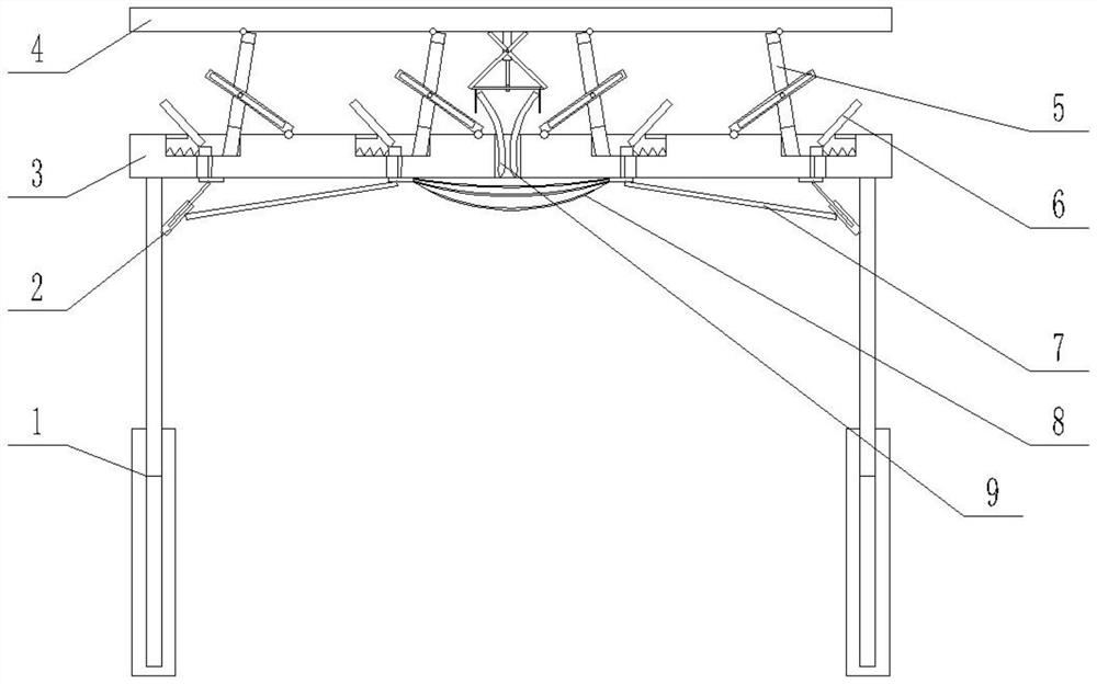
[0021] Specific implementation one: as Figure 1-Figure 8 As shown, this embodiment describes a temporary reinforcement device for coal mining construction roadway, including two hydraulic cylinders 1, two telescopic rods 2, a top plate I3, a top plate II4, four transmission devices I5, four support devices 6, two A connecting rod 7, a plurality of ropes 8 and a transmission device II9; the top plate I3 is fixedly connected to the upper ends of the two hydraulic cylinders 1; the transmission device I5 and the support device 6 are arranged on the upper end of the top plate I3, and the top plate II4 is arranged on the transmission The upper end of the device I5; the transmission device II9 is fixedly connected to the lower end of the top plate II4, a plurality of ropes 8 are arranged between the two supporting devices 6 in the middle, and the lower end of the transmission device II9 passes through the top plate I3 and is located at the upper end of the rope 8 .
specific Embodiment approach 2
[0022] Specific implementation two: as Figure 1-Figure 8 As shown, this embodiment is a further description of the specific embodiment 1. The top plate I3 includes a top plate main body 31 and four limit rods 36; The top of the main body 31 is provided with four through holes 33, and each through hole 33 communicates with the corresponding groove 32; the upper end of the top plate main body 31 is located between the two grooves 32 in the middle. In the vertical slot 35 , four limit bars 36 are fixedly connected to the inner wall of the vertical slot 35 .
specific Embodiment approach 3
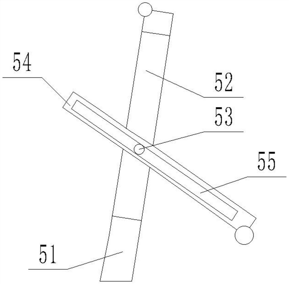
[0023] Specific implementation three: as Figure 1-Figure 8 As shown, this embodiment is a further description of the specific embodiment 1. The transmission device I5 includes a transmission rod I51, a rotating shaft 53 and a transmission rod II54; the lower end of the transmission rod I51 is slidingly matched with the corresponding groove 32, The top of the transmission rod I51 is hinged to the lower end of the top plate II4, and the transmission rod I51 is provided with a slideway 52, and the slideway 52 is fixedly connected with a rotating shaft 53; the transmission rod II54 cooperates with the slideway of the slideway 52, and the transmission rod II54 is on A chute 55 is provided, the transmission rod II54 is sleeved on the rotating shaft 53 through the chute 55, and one end of the transmission rod II54 is hinged to the upper end of the top plate I3.
PUM
 Abstract
Description
Claims
Application Information
 - R&D
- Intellectual Property
- Life Sciences
- Materials
- Tech Scout
- Unparalleled Data Quality
- Higher Quality Content
- 60% Fewer Hallucinations
Browse by: Latest US Patents, China's latest patents, Technical Efficacy Thesaurus, Application Domain, Technology Topic, Popular Technical Reports.
© 2025 PatSnap. All rights reserved.Legal|Privacy policy|Modern Slavery Act Transparency Statement|Sitemap|About US| Contact US: help@patsnap.com


