Eureka AIR delivers breakthrough ideas for toughest innovation challenges, trusted by R&D personnel around the world.

Sealing electric connector with clinging assembly capable of resisting external force collision

An electrical connector, anti-external force technology, applied in the direction of connection, connecting device components, circuits, etc., can solve the problems of skewed pins, inconvenient connection of electrical connectors, separation of electrical connectors, etc., to improve the sealing effect.

Pending Publication Date: 2022-08-09
中船永志泰兴电子科技有限公司
View PDF0 Cites 0 Cited by
  • Summary
  • Abstract
  • Description
  • Claims
  • Application Information

AI Technical Summary

Problems solved by technology

[0004] The purpose of the present invention is to solve the problem that the pins of the electrical connector in the prior art are easily skewed after being inserted and pulled out many times, which is not convenient for the connection of the two parts of the electrical connector, and the two parts of the electrical connector are easily impacted by external force The problem of being forced to separate, and a sealed electrical connector with anti-external collision and close-fitting components is proposed

Method used


Image

  • Sealing electric connector with clinging assembly capable of resisting external force collision
  • Sealing electric connector with clinging assembly capable of resisting external force collision
  • Sealing electric connector with clinging assembly capable of resisting external force collision

Examples


Embodiment Construction

[0024] The technical solutions in the embodiments of the present invention will be clearly and completely described below with reference to the accompanying drawings in the embodiments of the present invention. Obviously, the described embodiments are only a part of the embodiments of the present invention, but not all of the embodiments.

[0025] In the description of the present invention, it should be understood that the terms "upper", "lower", "front", "rear", "left", "right", "top", "bottom", "inside", " The orientation or positional relationship indicated by "outside" is based on the orientation or positional relationship shown in the accompanying drawings, and is only for the convenience of describing the present invention and simplifying the description, rather than indicating or implying that the indicated device or element must have a specific orientation, so as to The specific orientation configuration and operation are therefore not to be construed as limitations of...


PUM


Abstract

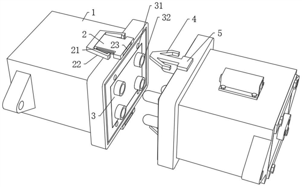
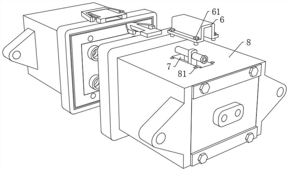
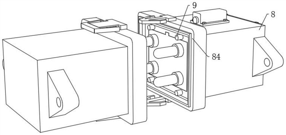
The invention discloses a sealed electric connector with a clinging assembly capable of resisting external force collision, and relates to the technical field of electric connector improvement, the sealed electric connector comprises a butt joint block and a connecting block, the side surfaces of the connecting block and the butt joint block are provided with accommodating grooves, the corners of the accommodating grooves are provided with transition fillets, the side surface of the butt joint block is fixedly connected with an insertion plate, and the insertion plate is fixedly connected with the butt joint block. Inserting rings are arranged on the side face of the inserting plate in a rectangular array mode, the side face of the connecting block is fixedly connected with an extending plate through screws, the side face of the extending plate is fixedly connected with an installing plate, and inserting needles are arranged on the side face of the installing plate in a rectangular array mode. The butt joint mechanism is arranged in the middle of the top of the butt joint block and the middle of the top of the connecting block, the clamping rod on the side face of the connecting rod is clamped into the side groove of the butt joint plate, rapid butt joint of the butt joint block and the connecting block is achieved, and the situation that the butt joint block and the connecting block of the electric connector are forcibly separated due to external force collision is avoided; meanwhile, the release rods on the two side faces of the butt joint plate can be used for rapidly achieving separation of the butt joint block and the connecting block.

Description

technical field [0001] The present invention relates to the technical field of improvement of electrical connectors, in particular to a sealed electrical connector with a close-fitting component resistant to external force collision. Background technique [0002] Electrical connectors are usually used in a variety of applications, such as for connecting two electronic devices. In addition to meeting general performance requirements, a particularly important requirement is that electrical connectors must achieve good contact, reliable work, and easy maintenance. The classification can be divided into circular electrical connectors and rectangular electrical connectors. Circular electrical connectors are used in military equipment (aviation and aerospace) due to their structural characteristics. Rectangular electrical connectors are more used due to their simple structure. on printed circuit boards of electronic equipment. [0003] The rectangular electrical connector is most...

Claims


Application Information

Patent Timeline
IPC IPC(8): H01R13/627H01R13/02H01R13/52
CPCH01R13/627H01R13/02H01R13/5219Y02T10/7072
Inventor 刘崎峰黄立罗煜
Owner 中船永志泰兴电子科技有限公司
Why Eureka
Eureka Blog
Learn More