
Portable grinding machine having improved vibration isolation mechanism

A sand mill and orbital motion technology, applied in the field of sand mills, can solve the problems of wear and tear of the claws and shorten the service life of the elastic claws.

Inactive Publication Date: 2004-05-12
MAKITA CORP
View PDF2 Cites 0 Cited by
  • Summary
  • Abstract
  • Description
  • Claims
  • Application Information

AI Technical Summary

Problems solved by technology

This rotation not only generates shear and bending stress at both ends of each claw (supported in the claw seat in the main body and base plate), but also causes wear of the claws, thereby shortening the service life of the elastic claws

Method used


Image

  • Portable grinding machine having improved vibration isolation mechanism
  • Portable grinding machine having improved vibration isolation mechanism

Examples


Embodiment Construction

[0019] Preferred embodiments of the present invention will be described below with reference to the accompanying drawings.

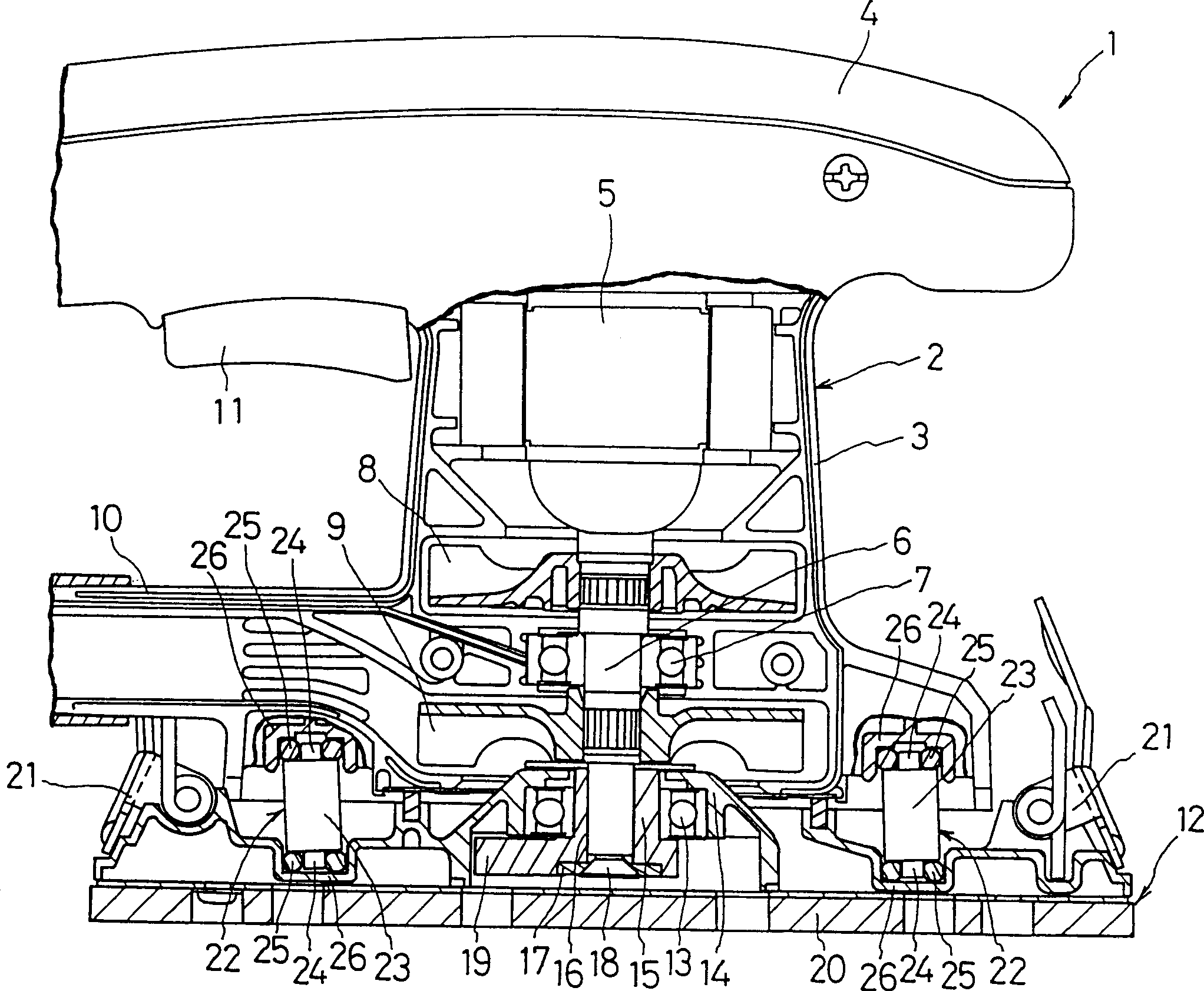
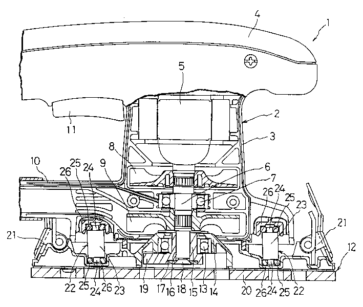
[0020] figure 1 It is a sectional view of the polishing sand mill 1 of the present invention. The polishing sand mill 1 includes a main body 2 and a base plate 12 disposed thereunder. The main body 2 comprises a pair of vertically split half shells 3 and 4, the shells contain a downwardly mounted motor 5, the output shaft 6 of which is supported by a ball bearing 7. The output shaft 6 of the motor 5 protrudes downwards into the base plate 12 from the bottom of the main body 2 . The cooling fan 8 is mounted on the output shaft 6 and above the ball bearing 7 to supply cooling air to the motor 5, and the dust suction fan 9 is also mounted on the output shaft 6 and below the ball bearing 7 to suck the main body 2 dust particles and other debris below, and send these waste materials to the dust suction hole 10 located on the left side of the main body 2 (a...


PUM


Abstract

A finishing orbital sander (1) includes a main body (2) and a base (12) provided below the main body. Provided between the main body and the base are a plurality of foot assemblies (22). Each assembly in turn includes a cylindrical or columnar foot (23) made of aluminum and a pair of rubber O-rings (25) at both ends of the cylindrical foot. Each foot additionally includes reduced diameter sections (24) at both ends, where the O-rings are disposed. The reduced diameter sections (24) are fitted in the O-rings and placed in recessed seats (26) provided in opposing surfaces of the main body (2) and the base (12), thus elastically supporting the aluminum feet (23) in the axial direction thereof. The axial dimension of each reduced diameter section (24) is made no longer than the thickness (i.e., the axial dimension) of the O-ring (25).

Description

[0001] related application [0002] This application claims priority from Japanese Patent Application No. 11-347847 filed on December 7, 1999, the contents of which are incorporated herein by reference. technical field [0003] The present invention relates to a sand mill, especially such a sand mill, which has a main body, which contains a motor and a base plate arranged below the main body, and the rotation of the motor transmits an orbital motion to the base plate for sanding workpieces. Background technique [0004] A typical orbital sander includes a main body containing a motor with an output shaft extending downwardly. This sand mill also includes a base plate that is eccentrically connected with the output shaft, so that the rotation of the motor is transmitted to the base plate through an orbital motion (that is: an eccentric circle motion) through the output shaft, so that when the sandpaper is installed on the bottom surface of the base plate, it can be Sand the ...

Claims


Application Information

Patent Timeline
IPC IPC(8): B24B23/04B24B41/00
CPCB24B23/04B24B41/007
Inventor 小田善一河合健一原章人稻井昌彦
Owner MAKITA CORP
Learn More