Electroluminescent display device and driving method thereof

A technology of electroluminescence display and electroluminescence layer, which is applied in the directions of electroluminescence light source, electric light source, lighting device, etc., can solve the problems of low response characteristics, deterioration of image quality, narrow viewing angle, etc.

Inactive Publication Date: 2004-05-26
SOLAS OLED LTD
View PDF0 Cites 0 Cited by
  • Summary
  • Abstract
  • Description
  • Claims
  • Application Information

AI Technical Summary

Problems solved by technology

However, liquid crystal display devices have problems of narrow viewing angle and low response characteristics.
As a result, the value of the current flowing through the organic EL element 31 is greatly changed, or in other words, the number of holes and electrons is greatly changed, so that even if an identical sig...

Method used


Image

  • Electroluminescent display device and driving method thereof
  • Electroluminescent display device and driving method thereof
  • Electroluminescent display device and driving method thereof

Examples


Embodiment Construction

[0048] Embodiments of the present invention will be described below with reference to the drawings.

[0049] In the first embodiment, an example of an organic EL display device in which one frame period in which an image of one frame is sequentially displayed is divided into four subframe periods and the light emission amounts of these subframes are divided into Set to a ratio of 1:2:4:8 to display 16 grade levels.

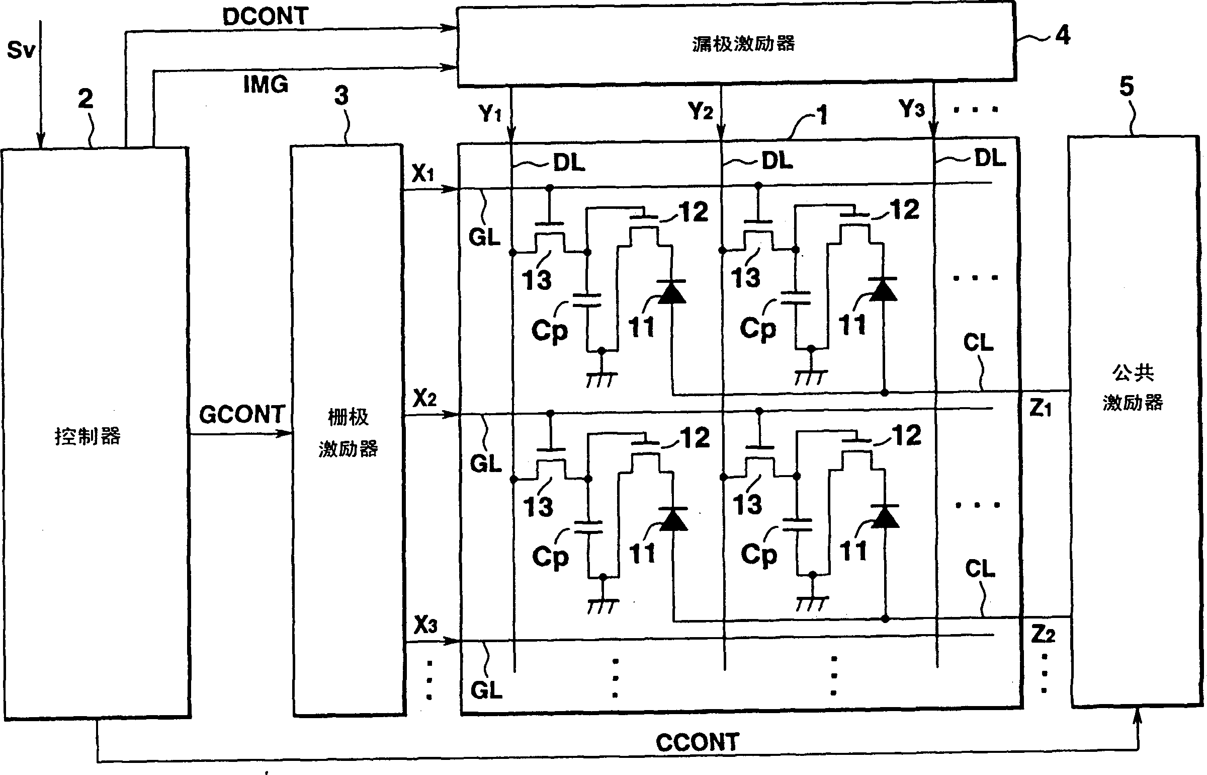
[0050] figure 1 is a block diagram showing the structure of an organic EL display device of this embodiment.

[0051] As shown in the figure, the organic EL display device includes an organic EL panel 1 , a controller 2 , a gate driver 3 , a drain driver 4 and a common driver 5 .

[0052] In this embodiment, the above-mentioned first group of electroluminescent elements is connected with the output common signal Z 1 The group of electroluminescent elements connected to the common line CL, the second group of electroluminescent elements is connected with the out...


PUM


Abstract

A controller stores image signals Sp represented as binary values for every unit of frame. The controller divides one frame into a plurality of sub-frames representing an image by image data of two gradation levels, in accordance with respective figures of the stored image signals Sp for one frame. The image data of two gradation levels for each of the sub-frames is written into capacitors Cp from a drain driver, for every row. When the image data is '1', a drive transistor is turned on. A common driver applies a voltage of a predetermined level for every sub-frame, to control the voltage applied between electrodes of an organic EL element. As a result, the organic EL element emits light with brightness which differs between sub-frames. Images of the sub-frames are visually synthesized, so that gradation is expressed in one frame.

Description

technical field [0001] The present invention relates to an electroluminescent device and its driving method, and more particularly, to a display device suitable for organic electroluminescent device or organic EL element hierarchical display and its driving method. Background technique [0002] As mobile computing becomes more popular, the demand for flat display devices is increasing. As a flat-panel display device, a liquid crystal display device is generally used. However, liquid crystal display devices have problems of narrow viewing angle and low response characteristics. [0003] On the contrary, attention has recently been paid to a display device realizing display by light emission using an organic electroluminescent element as another flat type display device having a wide viewing angle and excellent response characteristics. The pixels of the organic electroluminescent panel used in such a display device are respectively composed of an organic EL element 31, an e...

Claims


Application Information

Patent Timeline
IPC IPC(8): G09G3/20G09G3/32G09G3/36G09G5/02H05B33/00
CPCG09G5/02G09G3/2077G09G3/2081H05B33/00G09G2300/0842G09G3/2014G09G2310/027G09G3/2011G09G2300/0866G09G2300/0417G09G2320/043G09G3/2022G09G2360/18G09G3/3233G09G3/3655G09G2320/0223G09G3/3258G09G2320/0276H10K59/12G09G3/32
Inventor 山田裕康塩谷雅治
Owner SOLAS OLED LTD
Why Eureka
Try Eureka