Signal processing device

一种信号处理装置、信号的技术,应用在图像通信、阴极射线管指示器、电视等方向,能够解决电路规模增大等问题,达到防止图像样式模式化的效果

Inactive Publication Date: 2004-06-02
SOCIONEXT INC
View PDF0 Cites 0 Cited by
  • Summary
  • Abstract
  • Description
  • Claims
  • Application Information

AI Technical Summary

Problems solved by technology

[0013] However, if the number of bits is increased, not only the N-bit adder and limiter, but also the number of bits in the circuit that processes the offset-adjusted signal must also increase, and there is a problem of increasing the circuit scale.

Method used


Image

  • Signal processing device
  • Signal processing device
  • Signal processing device

Examples


Embodiment approach 1

[0036] A signal processing device according to Embodiment 1 of the present invention will be described below with reference to the drawings.

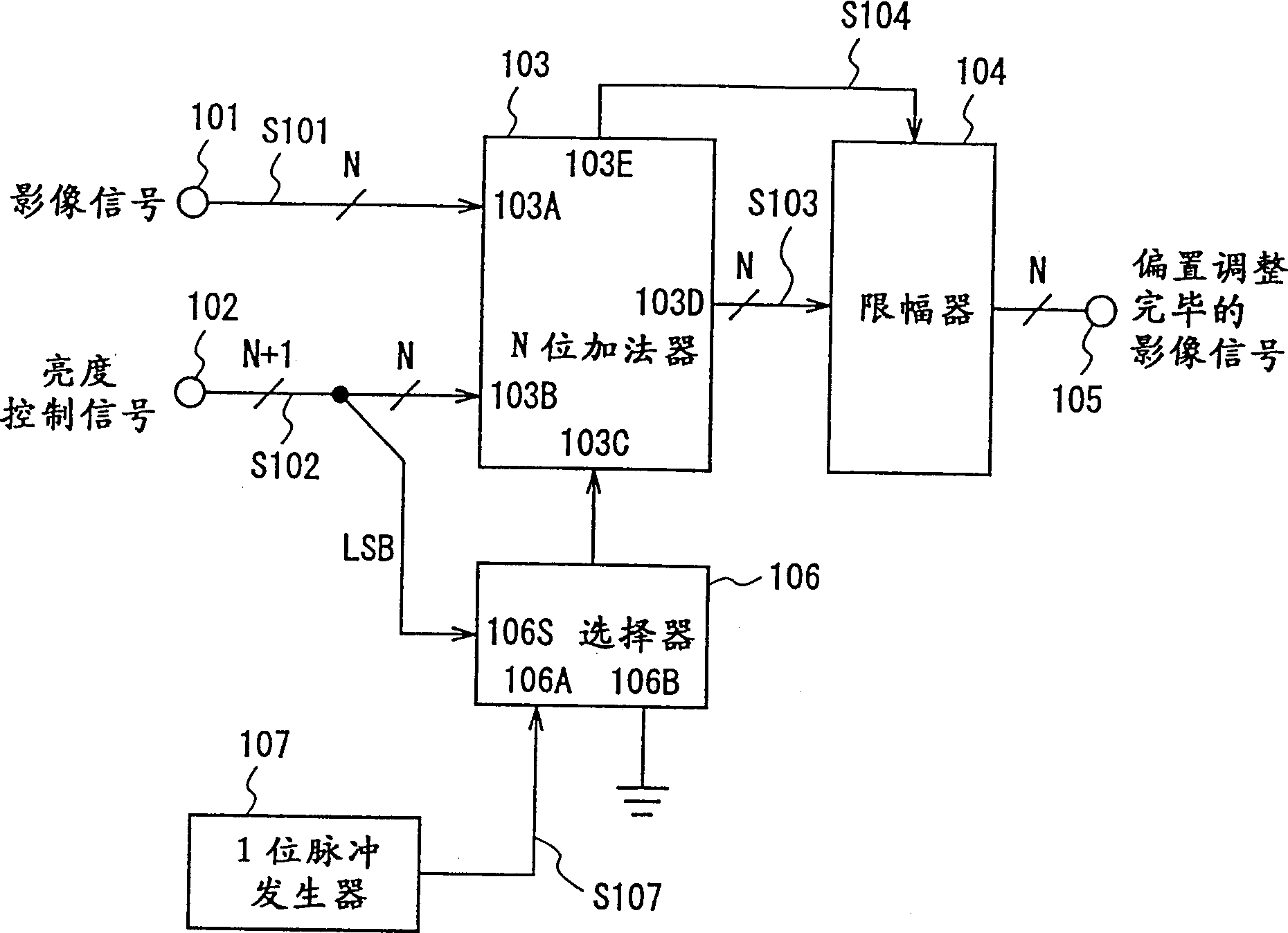
[0037] figure 1 It is a block diagram showing a signal processing device according to Embodiment 1 of the present invention.

[0038] exist figure 1 Among them, the structure of the signal processing device in this embodiment includes: an N-bit adder 103 , a limiter 104 , a selector 106 and a 1-bit pulse generator 107 .

[0039] The N-bit adder 103 adds the N-bit image signal S101 supplied to the input 103A, the upper N-bit signal of the N+1-bit luminance control signal S102 supplied to the input 103B, and the carry input supplied to the input 103C. Then, the addition result is output from output 103D as N-bit signal S103. And, in the addition operation, when an overflow occurs, the overflow 1 bit, that is, the most significant bit of the N+1 bits of the addition result is output from the carry output 103E as the carry output signa...

Embodiment approach 2

[0059] Next, a signal processing device according to Embodiment 2 of the present invention will be described with reference to the drawings. The signal processing device according to Embodiment 2 of the present invention is an example of the 1-bit pulse generator 107 according to Embodiment 1, and generates a 1-bit pulse signal using a vertical synchronization signal, a horizontal synchronization signal, and a pixel clock signal.

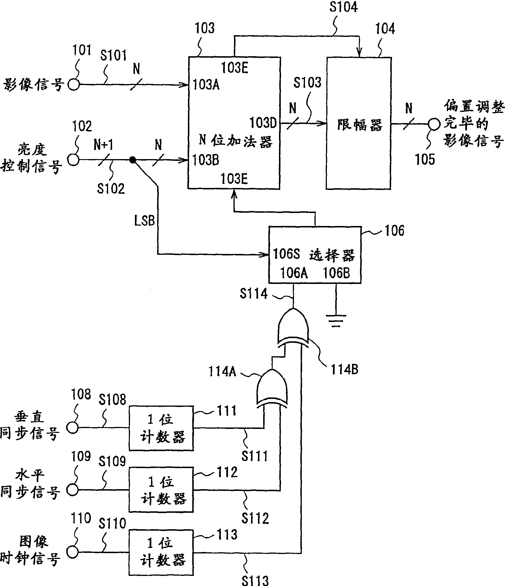
[0060] figure 2 It is a block diagram showing a signal processing device according to Embodiment 2 of the present invention.

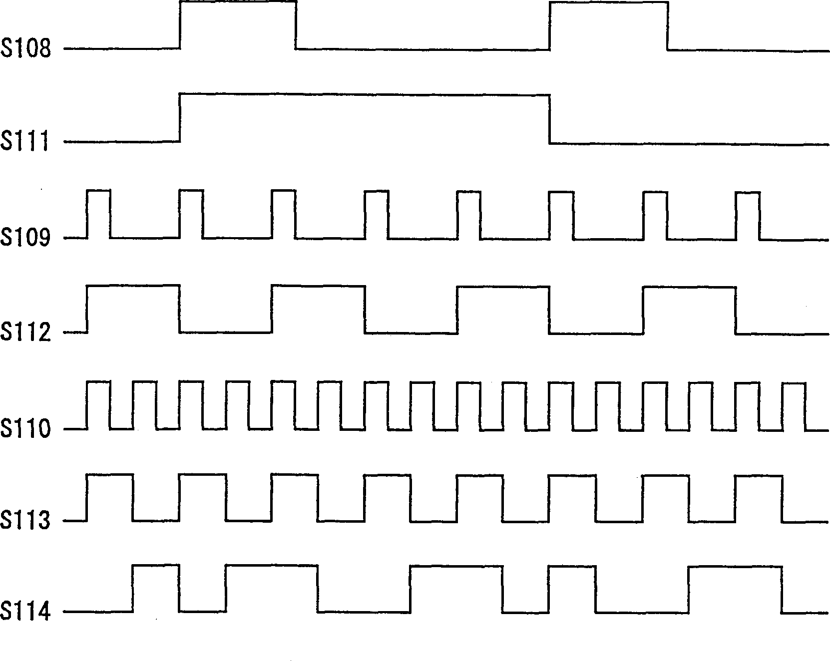
[0061] exist figure 2 Among them, the configuration of the signal processing device according to Embodiment 2 includes: N-bit adder 103, limiter 104, selector 106, 1-bit counters 111, 112, 113, and OR gates 114A, 114B. In addition, the configuration and operation of the N-bit adder 103, the limiter 104, and the selector 106 are the same as those in Embodiment 1, and the description thereof will not be repeated.

[0062]...

Embodiment approach 3

[0079] Next, a signal processing device according to Embodiment 3 of the present invention will be described with reference to the drawings.

[0080] Figure 4 It is a block diagram showing a signal processing device according to Embodiment 3 of the present invention.

[0081] exist Figure 4 Among them, the configuration of the signal processing device according to the third embodiment includes: an N-bit adder 103 , a limiter 104 , a selector 115 and a pulse generator 116 . In addition, the configuration and operation of the N-bit adder 103 and the limiter 104 are the same as those in Embodiment 1, and the description thereof will not be repeated.

[0082] The selector 115, according to the M-bit control signal, from 2 M Any one of the input signals is selected, and the selection signal is output to the N-bit adder 103. Here, one input of the selector 115 is grounded. In addition, M is an integer greater than 1.

[0083] Pulse generator 116, the ratio of the period duri...


PUM


Abstract

A signal processor for enhancing the offset accuracy of a video signal without increasing the number of bits of the circuit. An N-bit adder (103) adds a video signal (S101) and an offset value, i.e. the upper N bits of a brightness control signal (S102). A 1-bit pulse generator (107) generates a 1-bit pulse signal (S107) where 1 and 0 appear randomly with the same probability. A selector (106) selects the 1-bit pulse signal (S107) when the LSB of the brightness control signal (S102) is 1 and selects 0 of ground level when the LSB is 0. The selected signal is fed to the carry input of the N-bit adder (103).

Description

technical field [0001] The present invention relates to a signal processing device, and more particularly to a signal processing device for adjusting brightness of a video signal. Background technique [0002] The luminance adjustment of a video signal of a television receiver or the like is performed by adding and subtracting an offset signal to the video signal. [0003] Figure 7 It is a block diagram showing the configuration of a conventional signal processing device. [0004] exist Figure 7 Among them, the structure of the existing signal processing device includes an N-bit adder 1003 and a limiter 1004 . [0005] The N-bit adder 1003 adds the N-bit video signal S1001 input to the video signal input terminal 1001 and the N-bit brightness control signal S1002 input to the brightness control signal input terminal 1002, and uses the addition result as the N-bit signal S1003 from Output 100 3D output. Also, when an overflow occurs, the overflowed 1 bit, that is, the mo...

Claims


Application Information

Patent Timeline
Patent Type & Authority Patents(China)
IPC IPC(8): G09G5/10H04N5/57
CPCH04N5/57G09G2320/0626G09G2320/0606G09G5/10
Inventor 铃木秀利石川胜也伊藤启一国谷久雄
Owner SOCIONEXT INC
Why Eureka
Try Eureka