Method for adjusting frequency of piezoelectric resonator

A technology of piezoelectric resonance and resonance frequency, which is applied in the field of frequency adjustment of energy-trap piezoelectric resonance components, and can solve problems such as the difference in thickness of vibration electrodes and the reduction of electrical characteristics of components

Inactive Publication Date: 2004-08-25
MURATA MFG CO LTD
View PDF0 Cites 0 Cited by
  • Summary
  • Abstract
  • Description
  • Claims
  • Application Information

AI Technical Summary

Problems solved by technology

Therefore, due to the difference in thickness of the vibrating electrodes formed on both main surfaces of the piezoelectric plate, there occur...

Method used


Image

  • Method for adjusting frequency of piezoelectric resonator
  • Method for adjusting frequency of piezoelectric resonator
  • Method for adjusting frequency of piezoelectric resonator

Examples


Embodiment Construction

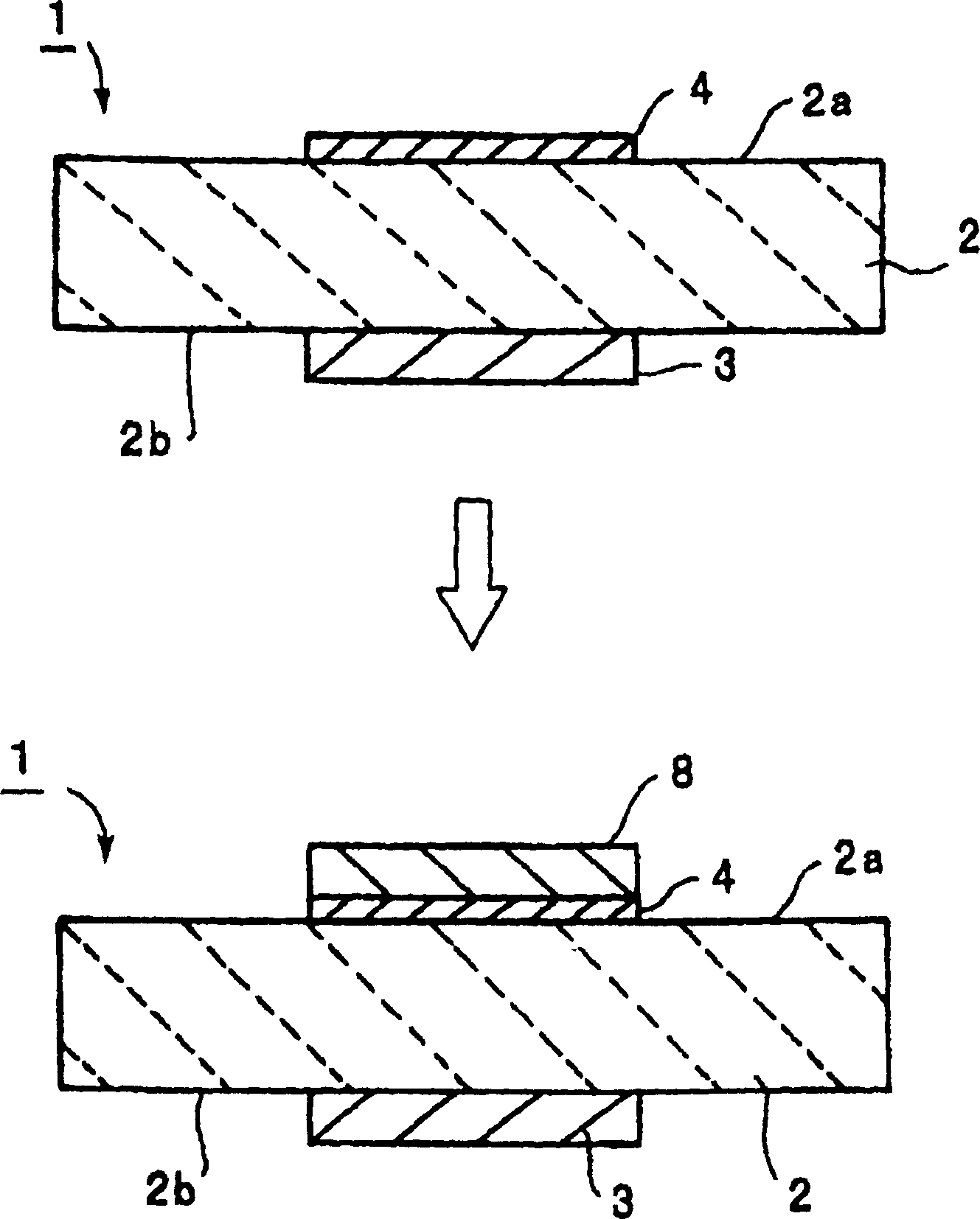
[0025] figure 1 is a cross-sectional view showing a preferred embodiment of the method of adjusting the frequency of a piezoelectric resonance element according to the present invention.

[0026] In this embodiment, an energy-trap type piezoelectric resonance element 1 is prepared. The energy-trap type piezoelectric resonant element 1 preferably includes a piezoelectric plate 2 formed from ceramics such as sphene zirconate ceramics. The first vibration electrode 3 is located on the lower surface of the piezoelectric plate 2 , and the second vibration electrode 4 is located on the upper surface of the piezoelectric plate 2 . The first and second vibrating electrodes 3 and 4 are arranged in such a manner that their front and rear surfaces face each other.

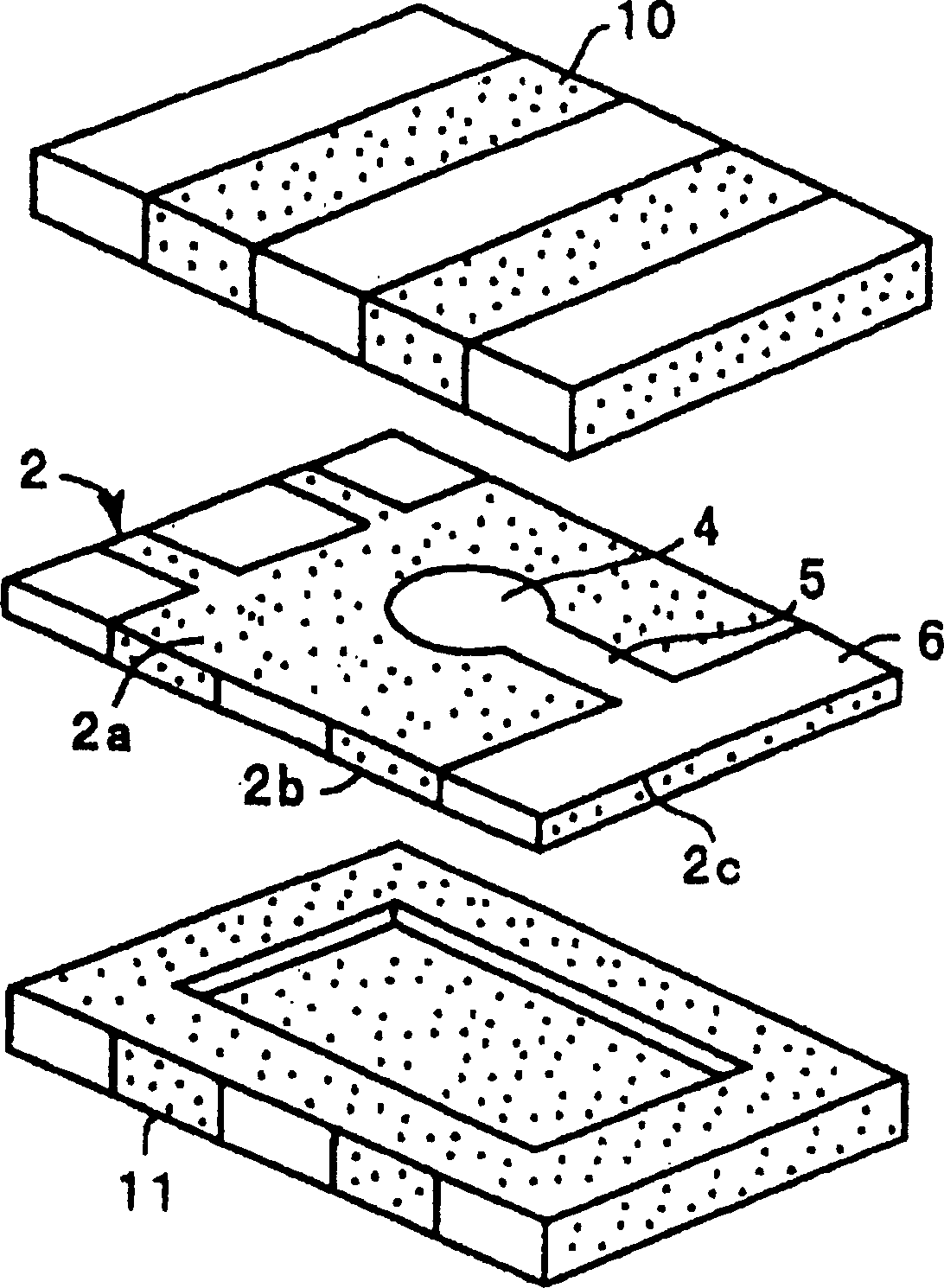
[0027] figure 1 The piezoelectric resonance element 1 is schematically shown. The piezoelectric resonant element 1 has the figure 2 in the structure. figure 2 is an exploded perspective view of the piezoelectric reson...


PUM

PropertyMeasurementUnit
Thicknessaaaaaaaaaa
Thicknessaaaaaaaaaa

Abstract

A method of adjusting a frequency of an energy-trap type piezoelectric resonance element includes the steps of preparing a piezoelectric resonance element including first and second vibration electrodes formed partially on both of the main surfaces of a piezoelectric plate, the thickness of the first vibration electrode being larger than that of the second vibration electrode, and modifying the first vibration electrode or the second vibration electrode in such a manner that the thicknesses of the first and second vibration electrode electrodes are substantially equal to each other such that the piezoelectric resonance element has a desired frequency.

Description

technical field [0001] The present invention relates to a method for adjusting the frequency of an energy-trap type piezoelectric resonant element, for example, using a thickness-extending vibration mode, a thickness-sliding vibration mode, or other vibration modes. In particular, the invention relates to tuning by controlling the thickness of a vibrating electrode. Energy-Trap Type Piezoelectric Resonant Frequency Method. Background technique [0002] Conventionally, energy-trap type piezoelectric resonance elements have been used for oscillators, piezoelectric filters, and other electronic parts. For such a piezoelectric resonance element, it is necessary to minimize vibrations in the resonance frequency and the center frequency. [0003] In manufacturing the above piezoelectric resonant element, vibrating electrodes are formed in a matrix pattern on the upper and lower surfaces of the piezoelectric mother substrate. The piezoelectric substrate is cut to produce individu...

Claims


Application Information

Patent Timeline
IPC IPC(8): H01L41/09H03H3/04H03H9/17
CPCY10T29/42H03H2003/0428H03H9/177H03H3/04
Inventor 中福祥人
Owner MURATA MFG CO LTD
Why Eureka
Try Eureka