
Piezoelectric resonance element

A piezoelectric resonance and piezoelectric element technology, applied in the direction of electrical components, piezoelectric devices/electrostrictive devices, piezoelectric devices or parts of electrostrictive devices, etc., can solve problems such as deterioration of elasticity

Inactive Publication Date: 2006-01-11
MURATA MFG CO LTD
View PDF1 Cites 0 Cited by
  • Summary
  • Abstract
  • Description
  • Claims
  • Application Information

AI Technical Summary

Problems solved by technology

If the content of conductive filler is increased instead, the elasticity will be greatly deteriorated

Method used


Image

  • Piezoelectric resonance element
  • Piezoelectric resonance element
  • Piezoelectric resonance element

Examples


Embodiment Construction

[0049] Hereinafter, the present invention will be apparent from the following description of specific preferred embodiments of the invention made with reference to the accompanying drawings.

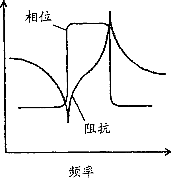
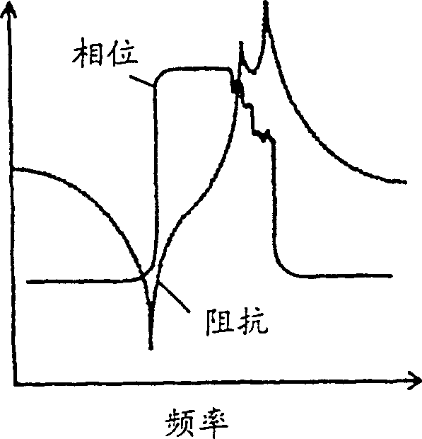
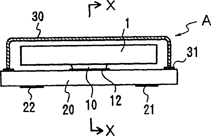
[0050] Figure 2 to Figure 4 An example of a piezoelectric resonance element according to a preferred embodiment of the present invention is shown. The most suitable piezoelectric resonant element of the preferred embodiment is a surface mount type oscillator comprising a piezoelectric element 1, a base 20, and a top cover 30.

[0051] A piezoelectric element 1 utilizes a longitudinal vibration mode, and as Figure 5 As shown, the piezoelectric element 1 includes a base 2 having a substantially rectangular shape. The most preferable structure of the base 2 has a plurality of piezoelectric layers 3 made of piezoelectric ceramic material and a plurality of internal electrodes 4 stacked alternately. Such as Figure 5 As shown by the arrow P of , the polarization is performed in the long...


PUM


Abstract

While suppressing that a vibration of a piezo-electric element propagates to a substrate by devising the composition of an electro-conductive support body, the piezoelectric resonant component which secures electroconductivity and can maintain a fall-proof shock property is provided. The piezoelectric resonant component has a substrate 20 on the top surface of which pattern electrodes 21 and 22 are formed, and on the lower surface of which it has electrodes 8 and 9. It has a piezoelectric element 1 using the length vibration on the substrate 20. Electro-conductive support bodies 10 and 11 are fixed to the length direction center section of the lower surface electrodes of the piezoelectric element 1. The connection fixation of these support bodies 10 and 11 to the pattern electrodes 21 and 22 of the substrate 20 is performed by electro-conductive adhesives 12 and 13. The electro-conductive support bodies 10 and 11 include an urethane resin which contains an electro-conductive filler, making the rate of content of the electro-conductive filler 75-85 wt %.

Description

technical field [0001] The present invention relates to piezoelectric resonant elements such as an oscillator, a phase detector, and a filter, and more particularly to a piezoelectric resonant element in which a piezoelectric element vibrating in a longitudinal vibration mode is mounted on a substrate element. Background technique [0002] Conventionally, an electrically conductive support is fixed to the center portion (node ​​portion) of the lower surface electrode of the piezoelectric element, which vibrates in the longitudinal vibration mode. When the support body is connected to the patterned electrode on the substrate via a conductive adhesive, the upper surface electrode of the piezoelectric element is connected to the patterned electrode of the other substrate via wire bonding. A piezoelectric resonance element having such a structure has been disclosed, for example, in Japanese Unexamined Published Patent Application JP10-200366. The electroconductive support is f...

Claims


Application Information

Patent Timeline
IPC IPC(8): H03H9/17H03H9/09H01L41/04H01L41/08H03H9/10H03H9/205
CPCH03H9/1014H03H9/0514H03H9/178
Inventor 草开重雅山崎武志小杉裕二
Owner MURATA MFG CO LTD
Learn More