

Method of directional reception using array antenna, and adaptive array antenna unit
An array antenna and directional reception technology, which is applied in the field of directional reception using array antennas and adaptive array antenna devices, can solve problems such as fast movement, slow movement, and difficulty in optimal tracking in the communication environment, and achieve the effect of directional transmission
- Summary
- Abstract
- Description
- Claims
- Application Information
AI Technical Summary
Problems solved by technology
Method used
Image

Examples
Embodiment 1
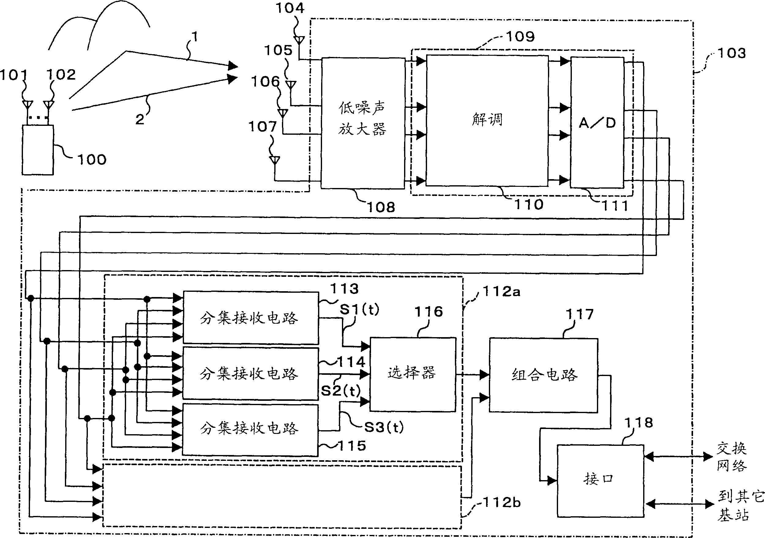
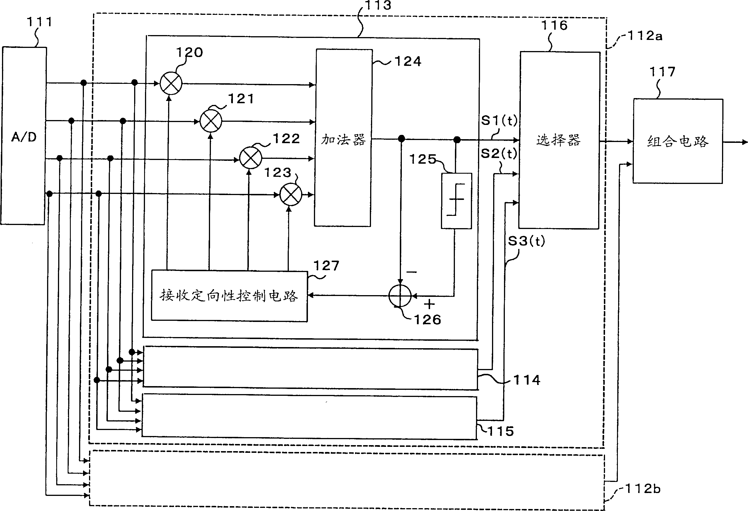
[0040] figure 1 is a block diagram of the adaptive array antenna device of the first embodiment.
[0041] This adaptive array antenna device multiplies signals received through a plurality of antenna elements by weighting coefficients Wi (i=1, 2, . . . , n), sums them, and outputs the resulting signals. Even if the antenna element itself has no directivity, it is possible to change the directivity by adaptively controlling the weighting coefficients. That is, it is possible to create multiple non-directional points (null points) in arbitrary directions.
[0042] For example, when the desired signal is from Figure 11 When the direction indicated by the reference numeral 701 arrives in , and the interference signal arrives from the direction indicated by the reference numeral 702, if the receiving directivity 703 points to the desired wave, the desired wave is strongly received, while the interference signal is received Weak reception, which makes it possible to improve the ...
Embodiment 2
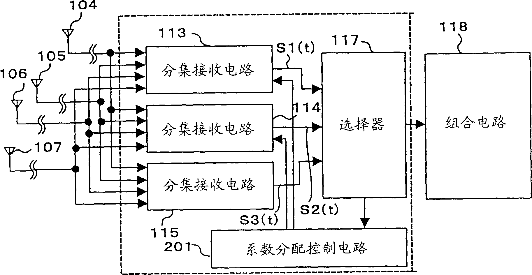
[0072] image 3 It is a block diagram showing the configuration of main parts of the adaptive array antenna device according to the second embodiment of the present invention.
[0073] image 3 The structure of the directional receiving circuit 200 is basically the same as figure 1 The directional receiving circuit 112a in is the same, but the directional receiving circuit 200 is different in that it is provided with a coefficient distribution control circuit 201 .
[0074] The characteristic operation of the directional receiving circuit 200 will be described below.
[0075] In this embodiment, whenever the selector 117 selects the output of a diversity receiving circuit, it updates the weights and weight updating coefficients of the other two diversity receiving circuits according to the weight and weight updating coefficient of the selected diversity receiving circuit , and this selection continues.
[0076] That is to say, the weight and the weight update coefficient of ...
Embodiment 3
[0090] Figure 5 It is a block diagram showing the configuration of main parts of the adaptive array antenna device according to the third embodiment of the present invention.
[0091] The basic structure and operation of the circuit of this embodiment are the same as those of the previously described embodiments. However, in the present embodiment, two-stage control is realized by operating the function of the control circuit 300; the first control is for high-speed convergence, and the second control is for precise convergence.
[0092] A detailed explanation is given below.
[0093] First, at the start of the receiving operation, the operation control circuit 300 operates the diversity receiving circuit 115 corresponding to the weight update coefficient μ3 that converges quickly. At the same time, it terminates the operations of the remaining diversity receiving circuits 113 and 114.
[0094] The selector 116 obtains the reception quality of the output signal S3(t) of th...
PUM
 Abstract
Description
Claims
Application Information