Ultrasonic cross shot peening of vanes on rotor

A shot peening device and shot peening technology, which are applied to the supporting elements of blades, vibration devices, explosion generating devices, etc., can solve problems such as loss of kinetic energy of particles, uneven shot peening, and increased shot peening time.

Inactive Publication Date: 2004-10-20
SN DETUDE & DE CONSTR DE MOTEURS DAVIATION S N E C M A
View PDF1 Cites 0 Cited by
  • Summary
  • Abstract
  • Description
  • Claims
  • Application Information

AI Technical Summary

Problems solved by technology

[0016] However, if the blade is longer when compared with the distance between two consecutive blades, especially if the relationship between the length and the distance between the blades is greater than 3, or when the height of the blade is greater than 100 mm and the shape of the blade is very curved, it is located in the inter-blade space Insufficient blade side peening at the bottom, this is because the particles have been sprayed many times and some have lost kinetic energy
In this way, the shot peening is not uniform and the peening time needs to be increased to ensure the minimum shot peening requirements of each point

Method used


Image

  • Ultrasonic cross shot peening of vanes on rotor
  • Ultrasonic cross shot peening of vanes on rotor
  • Ultrasonic cross shot peening of vanes on rotor

Examples


Embodiment Construction

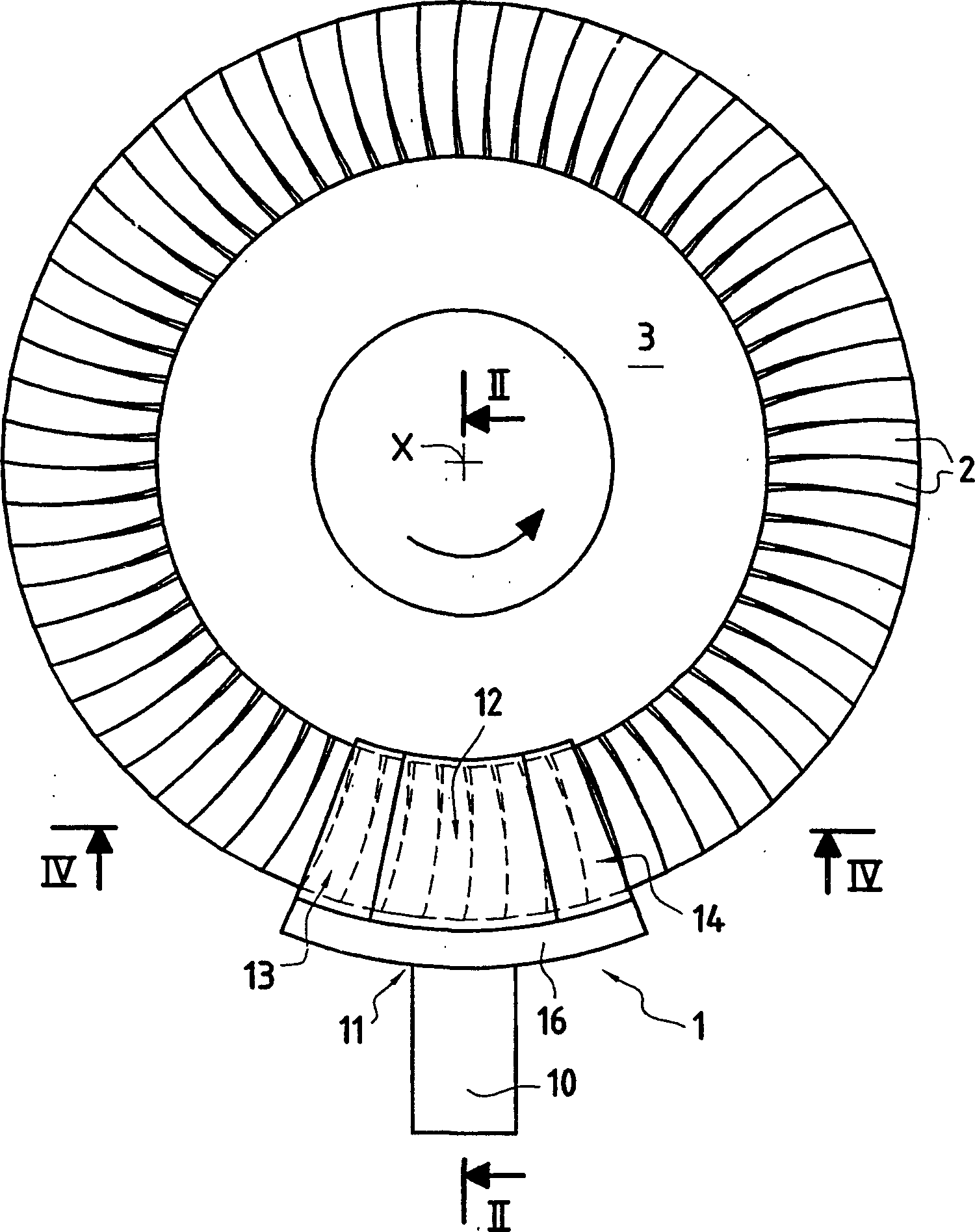
[0044] In these figures, number 1 is the shot blasting machine, the blades 2 are distributed radially around the flywheel 3, and the axis of the turbine is x. The flywheel 3 may be a single disc with blades or the flywheel of a turbine with movable blades. Blades 2 can also be parts whose surfaces should be shot-peened and have radially mounted flywheels 3 for supporting the parts to be shot-peened.

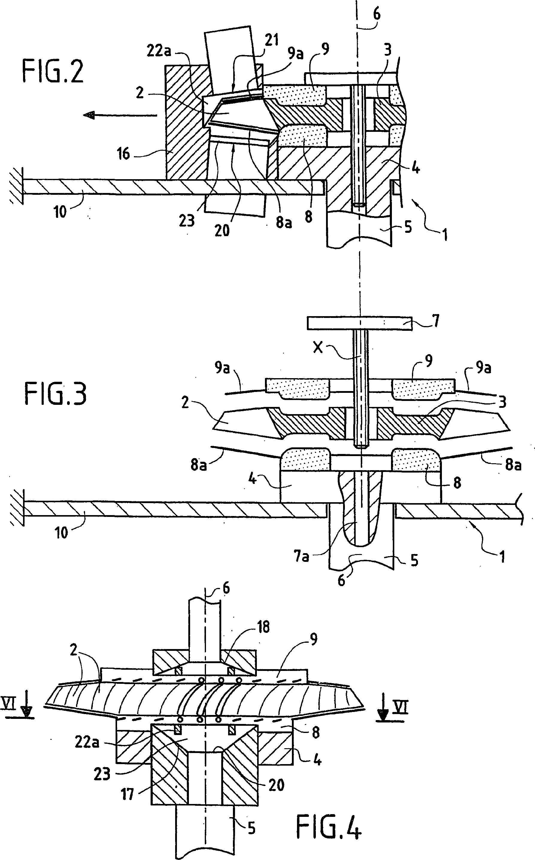
[0045] The shot blasting machine 1 basically has a rotating platform 4 supported by an axis 5 of axes 6 . The shaft 5 is driven in rotation about an axis 6, the driving means, such as a motor, not being shown in the figure. The flywheel 3 is fixed on the rotary platform 4 by means of the flange 7 and the reaming hole 7a of the shaft 6 punched out on the rotary platform, and its axis x should match the shaft 6 of the rotary platform.

[0046] Since this is very evident on FIGS. 2 and 3 , preferably a first annular disc 8 is located between the rotating platform 4 and the flywhee...


PUM


Abstract

The invention concerns a method for transverse ultrasound peening of blades (2) on a rotor which consists in driving in rotation the wheel (3) bearing the blades (2) about its geometrical axis (6) arranged substantially vertically and in causing the blades (2) to pass through a mist of microbeads produced by a vibrating surface (20) in an active chamber (12) arranged laterally relative to the wheel. The active surface (20) is located beneath the path of the blades (2). Preferably, the active chamber (12) comprises a second vibrating surface above the path of the blades (2). The invention also concerns a machine for implementing said method.

Description

technical field [0001] The invention relates to a method of blasting the surface of components using ultrasonic waves which are spread radially around the periphery of a flywheel, such as the blades of a turbine on a rotor. The invention also relates to a shot blasting surface treatment machine for carrying out the method. Background technique [0002] The term flywheel usually has the shape of a body of revolution centered on a geometric axis, which can rotate about its axis. [0003] In order to improve the fatigue resistance of mechanical parts, spraying particles are generally used to carry out shot peening on the surface. This technique is used extensively in aerospace to apply permanent pressure to the surface of very thin parts. This application of pressure can prevent cracks from appearing on the surface of the part or preventing cracks from intensifying, which can improve the fatigue resistance of the part. The technology uses a small angle relative to the perpen...

Claims


Application Information

Patent Timeline
Patent Type & Authority Patents(China)
IPC IPC(8): B24C1/10B24B1/04B24B39/00B24C5/08C21D7/06F01D5/28
CPCF01D5/286B24C5/005B24C1/10C21D7/06B24B39/00B24B1/04
Inventor 伯努瓦·让·亨利·贝尔特莱热拉尔·米歇尔·罗兰·盖尔德里克洛德·马塞尔·蒙斯玛丽-克里斯蒂娜·恩察马-埃图蒂
Owner SN DETUDE & DE CONSTR DE MOTEURS DAVIATION S N E C M A
Why Eureka
Try Eureka