Scroll type compressor
A compressor and scroll technology, which is applied in the field of compressors to prevent the reduction of operating efficiency, can solve the problems of excessive pushing force and overturning, and achieve the effect of preventing overturning.
- Summary
- Abstract
- Description
- Claims
- Application Information
AI Technical Summary
Problems solved by technology
Method used
Image
Examples
no. 1 Embodiment
[0086] Next, a first embodiment of the present invention will be described in detail with reference to the drawings.
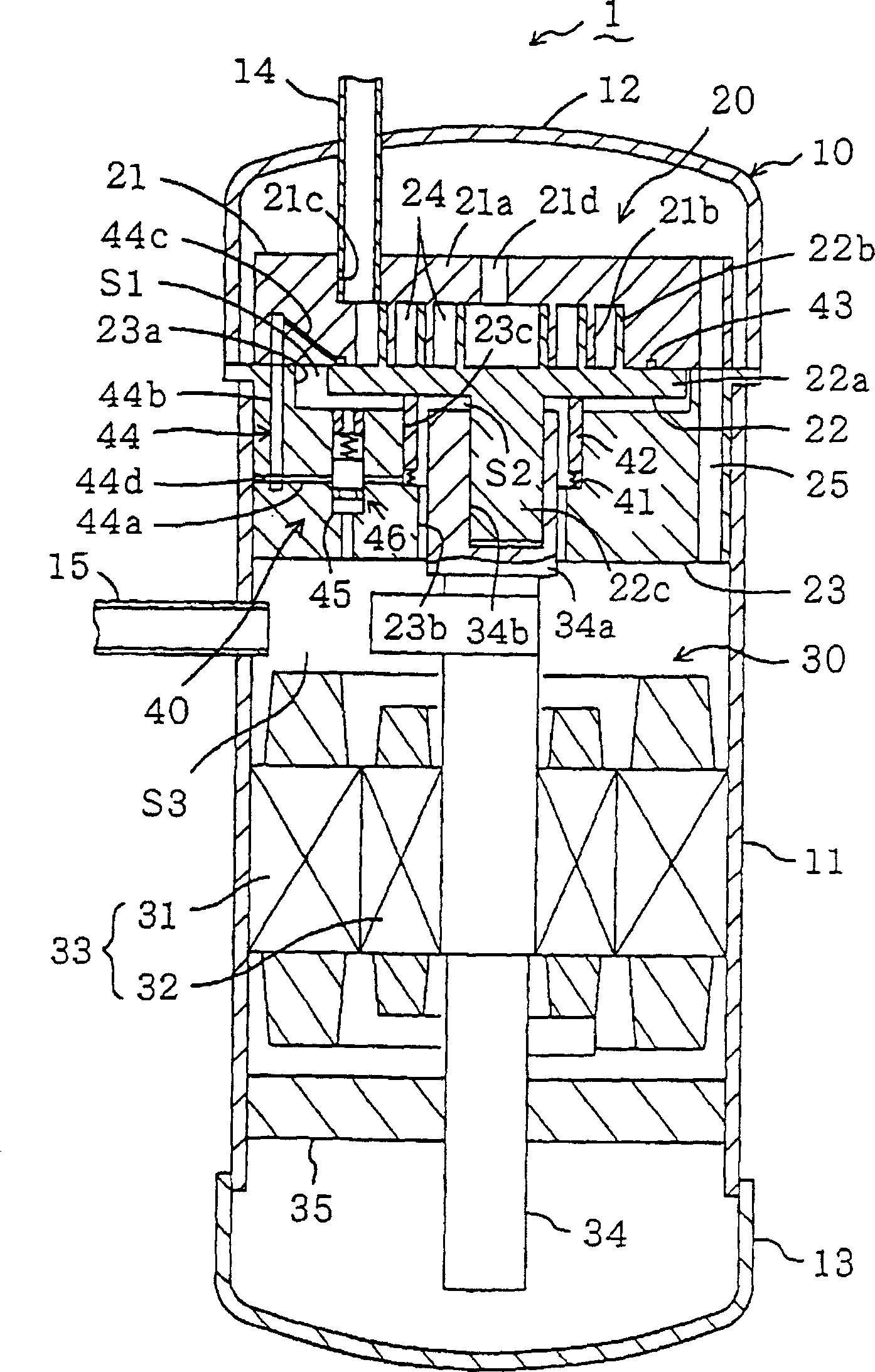
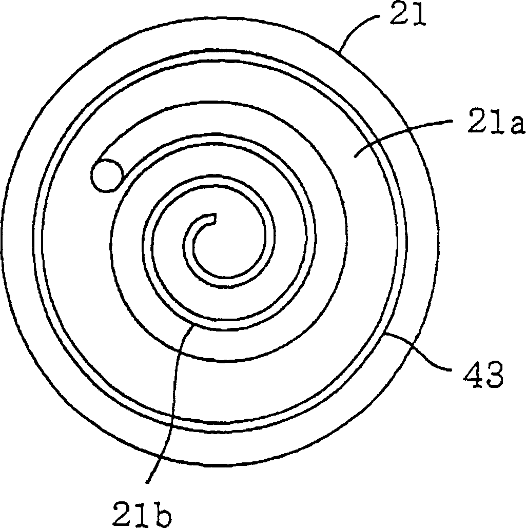
[0087] The scroll compressor (1) of the first embodiment compresses low-pressure refrigerant sucked in from the evaporator and discharges it to the condenser, for example, in a refrigerant circuit performing a vapor compression refrigeration cycle in an air conditioner or the like. The scroll type compression (1) as figure 1 As shown, inside the housing (10), a compression mechanism (20) and a drive mechanism (30) for driving the compression mechanism (20) are provided. The compression mechanism (20) is arranged in the upper part of the casing (10), and the driving mechanism (30) is arranged in the lower part of the casing (10).
[0088] The housing (10) is composed of a cylindrical tube (11) and disc-shaped end plates (12, 13) fixed to the upper and lower ends of the tube (11). The upper end plate (12) is fixed to a frame (23) described later, and the fram...
no. 2 Embodiment
[0121] Below, refer to Figure 8 A second embodiment of the present invention will be described.
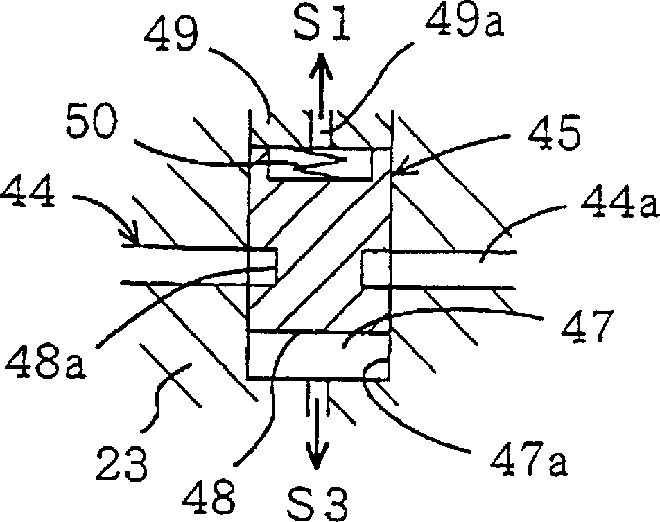
[0122] The scroll compressor (1) of the second embodiment is different from the first embodiment in the structure of the high-pressure oil introduction passage (44), and the other parts are the same as the first embodiment. Figure 8 This is an enlarged view showing the structure of the high-pressure oil introduction passage (44) and its peripheral portion.
[0123] The high-pressure oil introduction passage (44) of the scroll compressor (1) is formed at the end of the fixed scroll (21) in order to introduce the high-pressure oil in the second space (S2) as in the first embodiment. An annular oil groove (43) under the plate (21a), the high-pressure oil introduction passage (44) is formed on the fixed scroll (21) and the frame (23). The high-pressure oil introduction valve (45) in the first embodiment is not provided.
[0124] The high-pressure oil introduction passage (44) is ...
PUM
 Abstract
Description
Claims
Application Information
 - R&D
- Intellectual Property
- Life Sciences
- Materials
- Tech Scout
- Unparalleled Data Quality
- Higher Quality Content
- 60% Fewer Hallucinations
Browse by: Latest US Patents, China's latest patents, Technical Efficacy Thesaurus, Application Domain, Technology Topic, Popular Technical Reports.
© 2025 PatSnap. All rights reserved.Legal|Privacy policy|Modern Slavery Act Transparency Statement|Sitemap|About US| Contact US: help@patsnap.com


