Card connector

A technology of card connection and card insertion, which is applied to the parts of the connection device, the device for connecting, joining/disconnecting the connection parts, etc., which can solve the problems of the thinning of the card connection device and the increase in the size of the upper and lower directions, and achieve simple Effect of pull-in action or ejection action, reduction in number of parts, and reduction in manufacturing cost

Inactive Publication Date: 2005-07-20
ALPS ALPINE CO LTD
View PDF0 Cites 0 Cited by
  • Summary
  • Abstract
  • Description
  • Claims
  • Application Information

AI Technical Summary

Problems solved by technology

[0004] But, in the above-mentioned past card connection device, because the structure of loading mechanism is that the conveying roller is arranged on the top of the card channel or on the upper and lower sides to form the state of clamping the card channel, so the problem that exists is: only set the The space for the conveying rollers increases the size in the vertical direction, and it is impossible to make the card connection device thinner

Method used


Image

  • Card connector
  • Card connector
  • Card connector

Examples


Embodiment Construction

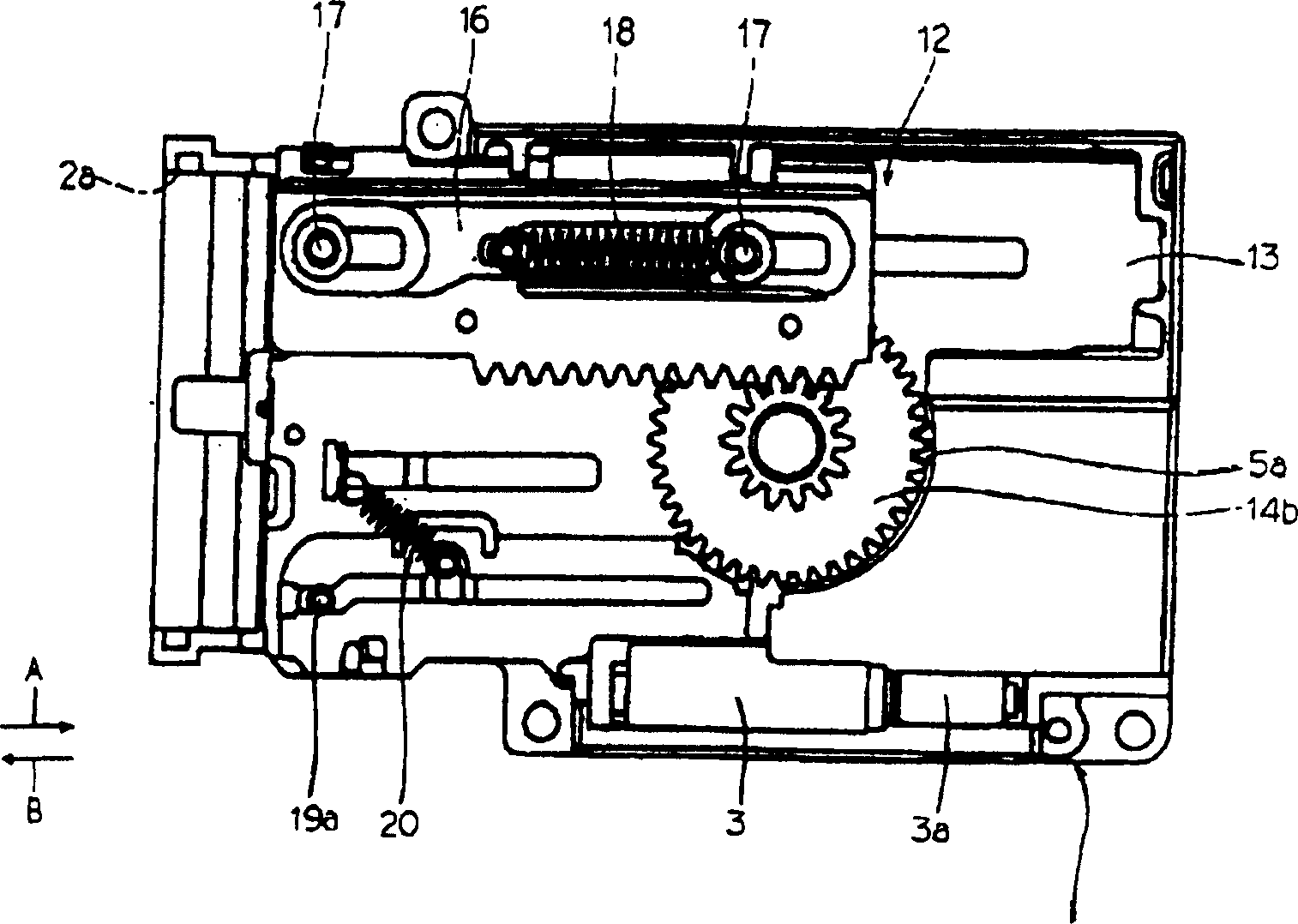
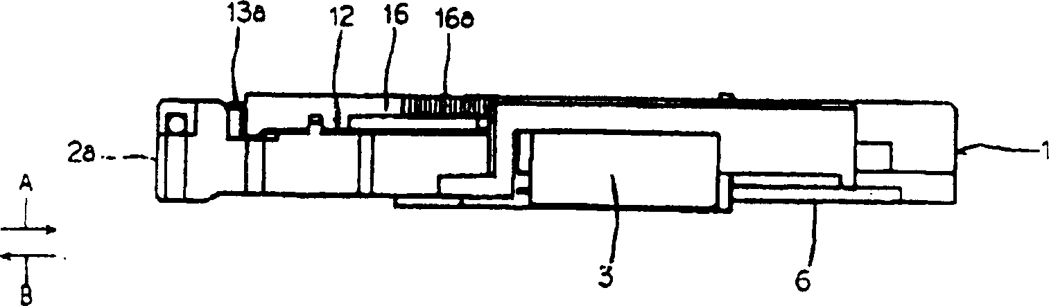
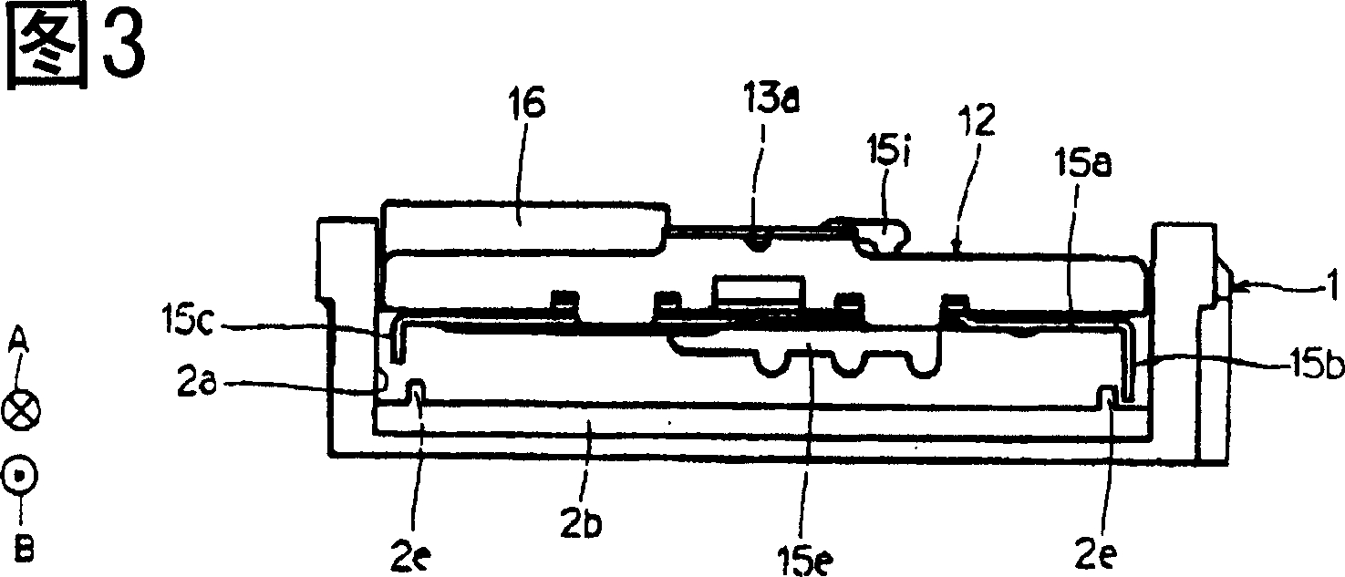
[0050] One embodiment of the card connection device of the present invention will be described in detail below with reference to the drawings. Figure 1 to Figure 32 It is for explaining one embodiment of the present invention. figure 1 is a plan view of a card connection device according to an embodiment of the present invention, figure 2 is a side view of the card connection device, and Fig. 3 is a front view of the card connection device, Figure 4 It is the front view of the card connection unit, Figure 5 is a plan view of the device main body included in the card connection device, Figure 6 is a plan view of the housing of the device main body included in the card connection device, Figure 7 It is a bottom view of the housing that the device main body has, and FIG. 8 is a plan view of the substrate that the device main body has, Figure 9 is a side view of a substrate included in the main body of the device, and FIG. 10 is a plan view of a loading mechanism includ...


PUM


Abstract

The invention provides a thin card connecting device. This card connecting device comprises a loading mechanism 12 to lead the card 21 into a device body 1 and ejecting the sent card 21 to the external of the device body 1 in the card lead-in direction A and the discharging direction B opposite to the lead-in direction A by the power of a driving motor 3, and an engaging member 19 mounted on the moving member 15 in a state of being engageable and disengageable to a recessed part 21b of the card 21, and the card 21 is moved in the lead-in direction A and the ejecting direction B with the moving member 15 by the engagement of the engaging member 19 with the recessed part 21b of the card 21.

Description

technical field [0001] The present invention relates to a card connecting device for connecting with a card having a contact portion, and more particularly to a card connecting device capable of drawing in and ejecting a card by using a loading mechanism. Background technique [0002] On the card connection device that equipment such as IC card and computer etc. are connected, a kind of loading (loading) mechanism is attached, so that the card inserted from the card insertion port is automatically delivered in the main body of the device. [0003] The loading mechanism, when inserting the card into the card insertion port, is arranged on the top of the card channel or on the upper and lower sides to form the transmission rollers in the clamping state of the card channel, which are driven by the motor to rotate, so as to insert the card into the device along the card channel. In the main body, when the recording or playback of information on the card is completed, the motor d...

Claims


Application Information

Patent Timeline
Patent Type & Authority Patents(China)
IPC IPC(8): G06K17/00G06K13/08
CPCG06K13/08G06K13/0831
Inventor 木原孝
Owner ALPS ALPINE CO LTD
Why Eureka
Try Eureka