Hand tool, in particular a screwdriver

A hand tool and tool technology, applied in the field of screwdriver or a wrench, thread tool, clamping tool or file, pliers, can solve the problems of wear and tool brittleness

Inactive Publication Date: 2005-08-17
WERA WERK HERMANN WERNER GMBH & CO KG
View PDF4 Cites 1 Cited by
  • Summary
  • Abstract
  • Description
  • Claims
  • Application Information

AI Technical Summary

Problems solved by technology

In this paper, one is confronted with the problem that, on the one hand, the wear resistance of the ribs makes the tool too brittle, while on the other hand, avoiding overall brittleness of the tool leads to softer ribs which suffer wear and tear

Method used


Image

  • Hand tool, in particular a screwdriver
  • Hand tool, in particular a screwdriver
  • Hand tool, in particular a screwdriver

Examples


Embodiment Construction

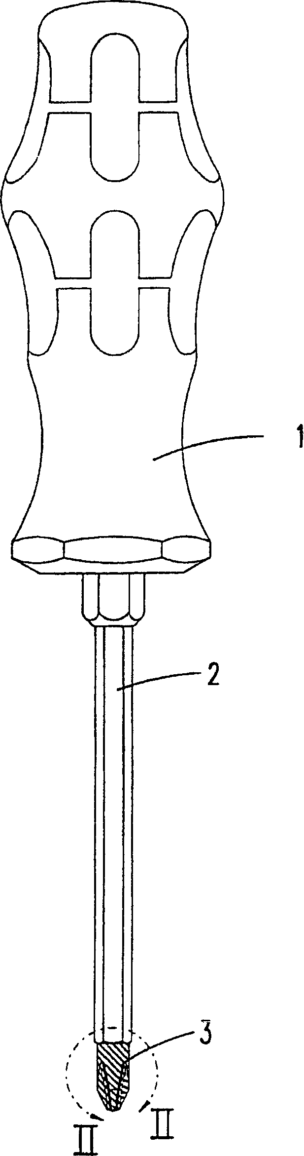
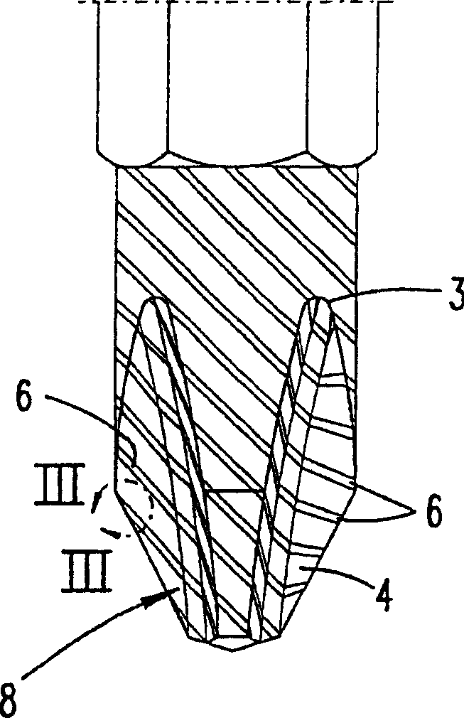
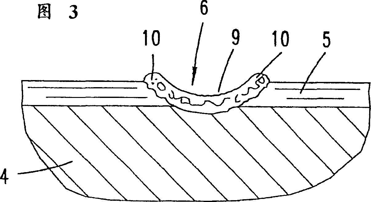
[0028] figure 1 with 2 The exemplary embodiment shown in is a screwdriver having a handle 1 and a blade 2 . At its end, the blade 2 has a working tip 3 . The working tip 3 forms a workpiece interface 8 . In this exemplary embodiment, the latter is in the shape of a cross. A plurality of parallel laser beams passing through the workpiece bonding surface 8 produces a plurality of linear contour fringes 6, which extend parallel to each other. The metal coating 5 applied to the steel core 4 serves to increase the strength of the material. This increase in the strength of the material in the region of the joining profile 6 of the material is accompanied by an increase in the surface hardness by approximately 100%. The energized region 6 is formed slightly further back than the non-energized region surrounding it. Application of the laser beam causes the melt to form along the path of the laser beam. Since the melt has a very high temperature gradient with respect to the bill...


PUM

PropertyMeasurementUnit
thicknessaaaaaaaaaa
thicknessaaaaaaaaaa

Abstract

The invention relates to a hand tool, in particular in the form of a screwdriver or a file, comprising one or more working surfaces with a grooved profile. According to the invention, the grooves are formed by recesses which are created using high-energy irradiation and which have border ribs. The border ribs can be formed by the edges of a fusion which immediately solidifies into a dish-shaped structure.

Description

technical field [0001] The invention relates to a hand tool, in particular to a threading tool, and preferably to a screwdriver or a wrench, and also to pliers, clamping tools or files, all of which have recesses on their working surfaces. [0002] The invention also relates to a method for machining the contour of the working face of a tool of the above-mentioned type. Background technique [0003] German utility model patent DE9500780.2U1 discloses a tool of this type. The utility model describes a screwdriver bit for Phillips head screws, wherein the working surface is machined into a linear shape with some recesses and protrusions alternately formed thereon. A groove profile is formed having ribs flanking the groove. In the process of producing this screwdriver bit, first; all the ribs are molded. Subsequently, the tool is hardened. The effects on the surface during quenching also have an effect on the ribs. In the case of excessive tool brittleness, where the stiff...

Claims


Application Information

Patent Timeline
Patent Type & Authority Patents(China)
IPC IPC(8): B23K26/00B23K26/38B25B13/00B25B15/00
CPCB25B15/002
Inventor 马丁·斯特劳赫
Owner WERA WERK HERMANN WERNER GMBH & CO KG
Why Eureka
Try Eureka